This article is about using the QRP Labs OCXO/Si5351A Synth kit to obtain very high precision using your U3S. This main part article (except this introduction) is by Pete ZL2IK and explains how he solved the problem of a frequency drift during his FSK CW transmission.
The QRP Labs OCXO/Si5351A Synth kit can be used in the U3S to provide an extremely stable frequency. However it requires some care to achieve this! It does not automatically happen, regardless of the rest of your system. The whole system needs attention. Now we have the ability to measure frequency to 0.01Hz resolution using tools such as Argo, and these weak-signal, narrow-bandwidth, slow-speed modes like FSKCW and WSPR are where frequency drift becomes critical and easily visible.
The U3S provides "Park mode" which means that you can set the Si5351A to output a frequency on its Clk1 output, which is not connected to the Power Amplifier, during key-up. The idea is that it keeps the Si5351A "warm" during key-up, providing less heat change to the Si5351A chip when the TX is keyed. IT applies to the basic Si5351A Synth kit, where the Si5351A's internal crystal oscillator is being used with the 27MHz crystal, as the reference for the PLL. Something like Park Mode 2, Park Freq 150MHz can be used to great effect, with the basic Si5351A Synth kit, to even get 0Hz WSPR drift reports on VHF bands. HOWEVER, it is important to note, the Park modes do not provide much (if any) benefit when using the OCXO/Si5351A Synth kit - because here the 27MHz oscillator is a separate transistor, with a buffer stage too, which isolates the oscillator from the Si5351A load changes.
In order to get the best possible frequency stability using the OCXO/Si5351A, there are several important factors.
1) CORRECT OCXO ADJUSTMENT - the frequency/temperature curve of the oscillator in the OCXO is a cubic curve with a turning point somewhere in the range 40-45C usually. The OCXO kit has to be properly adjusted so that the oven is at this temperature. The procedure is described in the manual, and it takes some time and patience to get it right! When properly adjusted, the sensitivity of the crystal frequency to small temperature changes is minimised. This is the critical first step to great performance of the unit!
2) THERMAL CONSIDERATIONS - if you are using multiple transistors in parallel in the PA, and the heat from those is flowing towards the OCXO, then quite possibly that will change the OCXO temperature and pull the frequency. The temperature controller in the OCXO is imperfect (naturally) and not instant either. So sudden application of lots of heat can throw it slightly off and cause a frequency change. Some attention might be needed to fit some insulation between the OCXO and the transistors, or any heatsink you have attached to the transistors. Or even just place a barrier of some kind between them so that air does not flow over the PA transistors towards the OCXO!
3) POWER SUPPLY - this is an important one and is the main subject of this article! You can refer to the OCXO/Si5351A Synth design page and the notes made there. In one of the tests there, you can see a dead-straight, drift-free 2 minutes on, 2 minutes off transmission on 30m (10MHz band). In order to get this straight, drift free (at least, within Argo's 0.01Hz measurement resolution), I had to eliminate 0.4Hz of initial drift. It came down to the power supply! I was using thin hook-up wire, about 0.5m of it between the U3 and the Power supply. When the load changes (on key-down), the current through the wire increases and the voltage drop across the wire will also change! We may be talking mV but it is enough to make a detectable difference! I changed to THICK wires and the drift dropped to 0.05Hz in 2 minutes. To get rid of that final last 0.05Hz of drift, I used separate voltage regulators for the PA and the rest of the U3. Voltage regulators are imperfect, the voltage change is non-zero when the load changes! It may be very small, but non-zero, and that is enough to cause a little frequency shift! Using separate voltage regulators for the U3 and the PA solves this problem.
Note that the U3S PCB already provides for this, because there are three separate power connector pads at the board edge. One is for the U3S digital circuits (processor, LCD). One is for the OCXO heater. One is for the PA voltage. They can be jumpered together, or you can use different supplies. The trace from the OCXO heater connection pad to the 10-pin header is thick, to reduce voltage drop when the OCXO heater load changes.
So, here's Pete's description of his U3S assembly!
U3S / OCXO Modifications by Pete ZL2IK
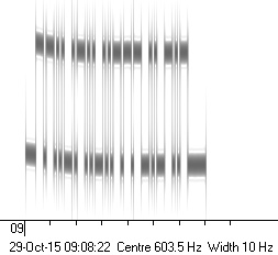
Firstly, here's an image provided by Pete, his callsign in FSKCW with 5Hz shift. The duration of this callsign transmission is 7 minutes. You can see that during the transmission, there is a frequency "droop", that is quite clearly visible. Less than 1Hz but still easily visible, and nice to try and eliminate it! Perhaps we shouldn't say "modifications" exactly, because this description is more about the power supplies than any actual changes to the U3S or OCXO. Anyway, from here on in Pete's own words.
I have spent a couple of days modifying my U3S, and tidying up the wiring to make it look presentable inside the case. I also used the spare panel switch to switch the power to the amplifier on and off.
Modifications:
After hearing about WA5DJJ’s problem of BOW’s at full power and when he decreased the power output, the BOW’s decreased, I remembered my earlier tests when the OCXO/Si5351, without any voltage on the amplifier, there were no BOW’s. On analysis, this led me to believe the problem lay with RF from the Amplifier being fed back into the OCXO and causing frequency shifts, via the common 5V supply rail. In fact this is how I frequency lock my Icom IC-R75 receiver! Fortunately the 3, supply rails can be easily separated (it is a feature of design anyway, by simply removing 2 links installed at assembly time.
This is how I did it:
1. I added three L7805CV, TO220 cased voltage regulators, inside the U3S case to minimise voltage drops in the supply leads to the equipment itself.
2. The 7805’s are bolted to the inside of the lower case half, and in a line just under the front edge of the installed GPS. My GPS board is mounted component side up. I use an external 3V3 amplified Antenna, not the supplied patch antenna. The patch antenna won’t work inside an aluminium case!
3. There is no need for an insulating washer under the mounting screw or a mica washer under the 7805 case; the cases are grounded anyway.
4. Each 7805 has a 33µF 50V Tantalum capacitor directly across its input and ground, and a 0.1µF 100V Mylar capacitor directly across its output and ground. Each capacitor is soldered onto the leads of the 7805’s to minimise lead inductance.
5. The capacitors across the terminals of the Regulators are essential to stop the RF getting back into the other supply rails, and indeed into the Regulators themselves. No other bypass capacitors are required.
The three 7805 Regulators feed:
|
The three 7805 Regulators feed: 1. The Amplifier (PA) – but could be exchanged for a 7809 or 7812 as the need arises. 2. The Logic Board and OCXO (+5 Volt rail). 3. The OCXO Oven Heater (Heat). |
|

To feed these three sections separately, remove the 2 links adjacent to C1 on the main board. One connects the PA to the +5V rail and the other connects the OCXO Oven Heater to the +5V rail. I installed a 4 way plug on the outer row of holes in the main board marked +PA/+5V/Heat/Gnd.
I installed a couple of Ferrite beads over the 4 wire supply cable (just in case) where it is routed over the top of the Display, the beads (and cable) push neatly into the gap between the Panel facia and the Display board.
I’m currently using a mains power supply whose output is switchable; it is capable of 2 amps maximum. I installed a high ripple current 10,000µF 40V capacitor across its output terminals to minimise AC ripple. The output voltage is 12V, and it does not change when running 250 mW from the U3S. This is the same supply I used to run the U3S directly, but switched to 5V.
Soak testing the unit today I have found there is minimal temperature rise from any 1 of the three 7805’s used, even when the supply was switched to 12 Volts. It will remain there.
I am very pleasantly surprised! The U3S no longer displays any tendency to cause BOW’s, Droops, or what-ever you want to call them. The output frequency remains constant for the whole 7 minutes it takes to send my call, and restarts at the same frequency every time. See attached 10 Min and 4 Hour Grabs, taken at full power – 250mW out, with the Amplifier on 5V. See Brgo329, you can see the Huff and Puff steps correcting the frequency! However the “railroad tracks” are still as straight as a die.
I am thinking about turning off the GPS Frequency Locking feature, as my OCXO is capable of keeping the frequency stable enough without the Huff and Puff feature of the GPS! – One can see the steps caused by the Huff and Puff between some of the callsign frames, it is quite coarse! Even when set to minimum correction. I think this highlights just how good the Reference Oscillator/Oven design really is, when setup correctly. Well done Hans.
Please keep your kits coming! You are keeping me occupied in my old age! Just like JY! Thanks again for your input.
Pete Mulhare
ZL2iK
Photos of Pete's U3S, and resulting frequency stability


