|
|
This Low Pass Filter (LPF) kit is based on the G-QRP technical pages design by Ed Whetherhold W3NQN. Kits are available for 16 bands 2200, 600, 160, 80, 60, 40, 30, 20, 17, 15, 12, 10, 6, 4, 2m and 222MHz. The kit uses a high-quality double-sided PCB with silk-screen, solder-mask and through-hole plating. The capacitors supplied with the kit are high-quality low-loss RF ceramics of the NP0 type (near-zero temperature coefficient). Designed for the U3 & U3S kits, U2 kit, relay-switched LPF kit, Arduino shield, or your own projects! |

The Low Pass Filter kit can handle at least 10W safely.


Printed instructions are NOT supplied with the kit. You can download the kit-building instructions for your PCB from the links below. PCB revision 1 has nothing written on the PCB. Revision 2 has "Rev 2" written on the PCB silk-screen in two places.
- Latest Rev 2: kit-building instructions, Click HERE for A4, and Click HERE for US Letter size.
- Latest Rev 2 in Japanese! CLICK HERE to download the fine Japanese translation by Toru JG1EIQ. See also his U3 here.
- Latest Rev 2 in Russian! CLICK HERE to download the fine Russian translation by Andrey R1CAD.
- Latest Rev 2 in French!! CLICK HERE to download the fine French translation by John F5VLB.
For kits supplied before January 2014:
- Revision 2: CLICK HERE to download the kit-building instructions for the earlier PCB revision 2 ("Rev 2" written in two places on the PCB).
- Revision 1: CLICK HERE to download the kit-building instructions for PCB revision 1 (nothing written on PCB)
To order: PLEASE VISIT QRP LABS SHOP!
LF band (600m and 2200m) kits:
Please see special notes in the instructions relating to the 600m and 2200m kits. There are many turns on the inductors in these LF kits and they cannot fit on the toroid. I did some measurements to determine whether the theoretical number of turns needs to be modified when the turns are wound messily on top of each other. The conclusion was that they do NOT.
The chart below shows measured inductance plotted against number of turns. The line is a rather imperfect curve since removing turns also resulted in some bunching and de-bunching of the remaining turns. The blue line is the theoretically predicted inductance. Note that the specification of the toroid permeability has a +/-5% tolerance and the difference between measured and theoretical values here is within 5%.
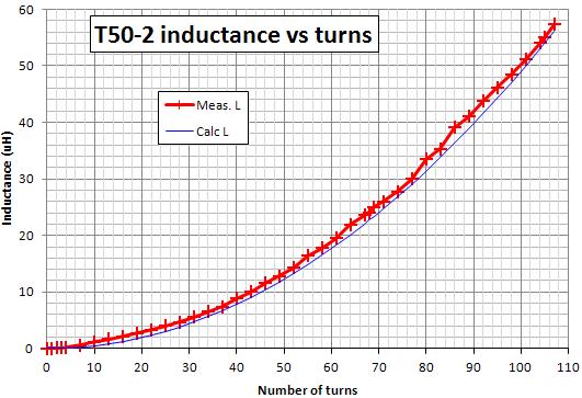
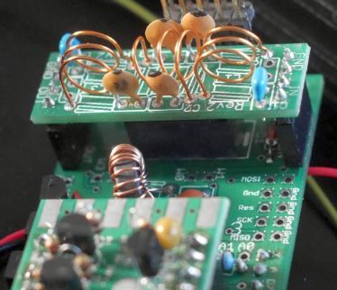
The following are photos of two coils I made for measurement while producing the above chart. I hope that they illustrate my winding method - just bunching all the turns on top of each other seems to work fine without damaging the predicted inductance. I think that the important thing is to wind evenly around the core - so that for example, the 48'th turn is near to the 52'nd and so on. But the 75'th turn of a 100-turn coil should be 90-degrees away from the 50'th turn.
The left photo is a 70-turn inductor for a 600m filter, and the right photo is a 105-turn inductor for a 2,200m filter. Please click the photos to open up a larger version!


Components and performance
The components provided in this LPF kit are tested and selected for good RF performance, to ensure minimum loss below the cut-off frequency and good attenuation outside it.
Capacitors: the provided capacitors are low-loss Class-1 dielectric RF types (also known as CC4), with low temperature coefficient (also known as NP0 or C0G). All the capacitors supplied have a voltage rating which is adequate for up to 10W RF.
Toroidal cores since January 2019 use highest quality micrometals toroids supplied via https://kitsandparts.com/ (US) and Vishay brand NP0 50V capacitors supplied by Digikey US.
Toroidal cores in kits supplied from January 2014 - December 2018 used toroids manufactured by a Micrometals competitor. These were more easily available outside the US. However, in order to ensure continued high quality and performance of the kits, the characteristics of these toroids, and the performance of the resulting LPF's have been extensively tested in 10m, 80m and 160m versions of the LPF kit (for T37-6, T37-2 and T50-2 toroids respectively). These tests are documented in this PDF file, please click.
Performance: please CLICK HERE to visit the page documenting the performance of the LPF filters, and the output spectrum of the Ultimate3 kit when using using them.
30m Response curves by Ulli DC8SE


2m LPF by Tor SM6FWF
Note: this 2m kit design is now also available in the shop!
Tor SM6FWF reports good results with the Ultimate3S kit on 2m band WSPR. He used a 2m filter built on the usual QRP Labs LPF PCB. The capacitor values are 22pF at the ends (C1 and C4), and 43pF in the middle (C2 and C3), each 43pF capacitor is made from 33pF + 10pF in parallel. The inductors are 3 turns of wire wound on a 6mm diameter air-core, as pictured. The middle coil is a little longer (for lower inductance). Tor writes:
Thanks for the help with the filter, I used 3 turns of diameter ca 6mm, the middle coil a little longer, capacitors 22pF and 33+10pF.
I just checked the inductance with a small meter for surface mounted devices, compressed the coils a little to get good enough values, may be wrong but not so much.
2m LPF testing by Rick NM3G
Rick NM3G built this 2m filter exactly, and tested it on his spectrum analyser with tracking generator. The response curves are shown below and are good. He reports 2nd harmonic attenuation of 46.25dB (288MHz) and 42.75dB at the 3rd harmonic (432MHz). Fundamental insertion loss (144MHz) was 0.14dB. Photos are shown below.


DDS VFO DC receiver by Viktor HA7JVV
Viktor HA7JVV writes:
In the last week I have built a DDS VFO DC receiver.
I did not want to suffer filter construction, so I designed my receiver to be compatible with your LPF kit.
This kit LPF amazing! Built easily but still excellent! With this simple receiver I hear many Japanese stations (56-59) with my end feed long wire antenna (10.5 meters).
I love QRP Labs constructive modules!


Toroid-winding tutorial video
Thanks to Chris WX5CW for sending a link to this useful video showing one way to wind toroids!
4m LPF by Luci 9A1Z
Luci uses this 4m LPF in the official Montenegro PI4 beacon, as 4O0BCG. You can see some photos of this beacon on the Ultimate3 Builders' photos page. The picture below shows his calculations of component values. The outside inductors are 119nH; the middle inductor is 126nH. The capacitors are 100pF, 141pF, 141pF and 100pF. Luci provides coil winding details for the air-wound inductors. If equipment to measure inductance is not available then just use one fewer number of turns.


4m LPF by Ken G4APB
Note: this 4m LPF design is now also available in the shop!
Ken G4APB also has a 4m LPF design that works. His component values are: C1/4=10pF, C2/3=56pF, L1/3 = 6t on T37-6 yellow core, L2=7t on yellow core. Ken reports that a single BS170 PA with 10V PA supply voltage produces 20dBm on 4m.
Ken's configuration has been built and tested by QRP Labs. We used an 8pF and 2pF capacitor, not having a suitable 10pF capacitor on hand. The results are as shown below. The 3dB cut-off is something around 75 or 80MHz and given the measurement set-up, the results are exactly as expected. So this filter with Ken's values was verified as suitable for 4m.


4m LPF measurement by Luc LX1IQ


222MHz LPF by Rick NM3G
Note: this 222MHz LPF design is now also available in the shop!
Rick NM3G describes a 222MHz LPF on this page - basically the capacitors are the same as the above 2m LPF design but the inductors are less. Read more...