|
|
This clock kit is based on the same hardware as Ultimate3/3S QRSS/WSPR kit and a special firmware version. A GPS receiver module such as the QLG1 can optionally be connected for precision time-keeping. The display format is customisable; as well as time and date, you can also choose to display GPS data (e.g. location, number of received satellites, etc). |

This is a shack clock and sidereal clock kit which can optionally also be connected to a GPS receiver module such as the QLG1 to provide precise time. Alternatively it can be used standalone or with a different 1 pulse per second (pps) signal source.
This clock's features include:
- GPS date, time and other parameters, using a GPS module such as the QRP Labs QLG1
- Location (latitude, longitude and altitude) and Maidenhead grid square or subsquare
- Display of UT date, time and weekday
- Display of local date, time and weekday
- Display of Greenwich and Local Sidereal Time
- Configurable time zone offset, with display of local date and local time
- 10 alarms, which can be configured to switch on and off 6 different external relays or output signals
- Flexible configuration of the display contents
- Multiple messages can be set up to display sequentially on the display lines, for configurable duration
- Support for 4-line displays
- Two Analogue temperature sensors an optionally be connected to the kit, so that temperature measurements can be displayed (for example, indoor and outdoor temperature).
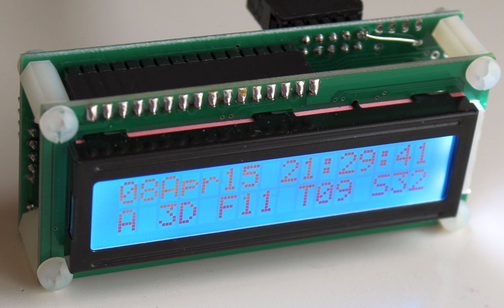
The contents of the display are completely configurable; the photographs on this page show the default configuration of the clock display.
Documents
These are the instructions for the latest PCB revision and Firmware version. Please check your PCB and your firmware revision. If you have an earlier version use the correct documents in the next section.
Assembly manual (PCB "QCU Rev 1" or "QCU Rev 3" or "QCU Rev 4")
Operation manual (firmware c1.03)
Documents: older PCB and Firmware versions
Assembly manual (PCB "U3S Rev. 2", old U3S PCB)
Assembly manual (PCB "Rev. 5", old U3 PCB)
Operation manual (firmware c1.02a)
Operation manual (firmware c1.01 and c1.01a)
Firmware version history
| Version | Date | Features |
| c1.03d | 28-Oct-2020 | - Bug fix: Incorrect weekday calculation (again) - Bug fix: Fixed occasional issue where sometimes GPS info shows as -- - Bug fix: Alarms functionality, minor improvements and fixes |
| c1.03c | 16-Feb-2020 | - Negative altitudes in the #AF tag are now displayed (were previously set to just 0) - Bug fix: incorrect weekday calculation (affects #DA, #D3, #LA, #L3) - Bug fix: incorrect local date month on new year's eve for locations who are behind GMT |
| c1.03b | 16-Sep-2019 | - Bug fix: incorrect weekday calculation (affects #DA, #D3, #LA, #L3) - Bug fix: Occasional quick change of #GT and #GS rapidly between small and large numbers |
| c1.03a | 09-Sep-2019 | - Bug fix: Typo in day of week, "Saturday" was written "Saturdayday" |
| c1.03 | 06-Sep-2019 | - Added #UH, #UM, #US tags for Greenwich Sideral Time - Added #TH, #TM, #TS tags for Local Sidereal Time - Added #AF tag for altitude in feet - Added #DA, #D3 tags for UT weekday in full and 3-letter abbreviation respectively - Added #LA, #L3 tags for Local weekday in full and 3-letter abbreviation respectively - ADC now averages 100 samples to reduce noise (for temperature calculation etc) - Bug fix: Local date now fixed (was showing yesterday) |
| c1.02a | 08-Oct-2018 | - Bug fix: T1 & T2 were overriden by relay outputs. Now if the relays 1 and 5 are not configured on any alarms, the inputs can be used for temperature measurement |
| c1.02 | 04-Oct-2018 | - Add tags #ND, #NM, #NY for local date days, months and years (taking into account local time offset) - Upgrade Clock firmware to require only .hex installation, as for other QRP Labs kits - Added 10 alarm settings, each with start/stop that can control I/O and relays, and be enabled individually - Add Alarm Local setting, when ON the alarm times use local time (otherwise UT) - Local time offset configuration parameter changed to 3 digits (enough for all world timezones) - Add tags #R0 to #R5 which display 1 or 0 to show the state of the specified relay or I/O signal - Add tag #GD for GPS Ground Speed - Add tag #GC for GPS Ground Course - Add tag #AL to show bell icon if the alarm is enabled - Add tags #DT and #DN for Decimal degrees latitude and longitude - Add tags #ST and #SN for Degrees Minute Seconds latitude and longitude format - While running, Right button now toggles enabled state of alarms - Enable Alarms setting is now an ON/OFF selection - Add lowercase characters, if enabled by new "Lowercase" setting - Six new tags #I0 to #I5 which display raw ADC inputs - 10 new tags #A0 to #A9 which display alarm times - Optional extended tag formatting ##slNN where NN = tag, s = start character, l = length - GPS Checksum validation, same as Ultimate3S, if enabled by new "GPS Checksum" setting - Display "Setting up" message during operator-initiated factory reset - Bug fix: 6th character of Maidenhead locator incorrect in some cases - Bug fix: Line1 Factory reset was missing last two characters - Bug fix: Properly display temperatures of 100 or over |
| c1.01a | 01-Dec-2015 | - Just a recompilation under latest AVR Studio on Win 10. No new functionality or changes! |
| c1.01 | 31.Aug.2015 | - Support for 4 x 20 LCD. - Local Time Offset entry, in minutes. - #LH and #LM tags for local time hours and local time minutes. - #H2, #AP tags for local time hours in 12-hour format, and "AM"/"PM" display. - Added alarm function: Alarm, AlarmOn params. To cancel Alarm, press Right button. - Bug fix: Factory reset copied 2nd display line on 1st, and did not reset second display line - Bug fix: Factory reset put temperature calibration values to non-Factory values. - Bug fix: If GPS latitude/longitude displayed on top row, it could cause some display corruption of row 2 in some cases. - Bug fix: Long message strings, overwrite the top LCD line when looping through menu. |
| c1.00 | 08.Apr.2015 | - Original kit firmware version |
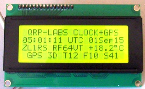
4-line display
The clock firmware from firmware version c1.01 onwards supports a 4-row 20-column LCD. Each line can be configured, just the same way as the standard 16 x 2 LCD module supplied in the kit. The following photograph shows a 4-line clock display by Bob ZL1RS.
Beautiful customised build by Henk PE4H
The photographs below show Henk PE4H beautifully made clock. Like Bob ZL1RS above, Henk also uses a 4-line display. His enclosure includes power supply and QRP Labs QLG1 GPS. A unique step by Henk, was to incorporate lower case characters into the display. The configuration of the clock supports upper case characters only. But Henk read out the EEPROM .eep file, and edited it in AVR Studio 7's hex editor, replacing the desired upper case characters with lower case ones.


Very nice shack clock built by Ed WA4MZS
Ed sent me some photographs of his project (click thumbnail pictures below) and writes:
"The case / cabinet is a Bud PC-11406. Front panel was painted with Rustoleum 'Charcoal Gray' (a close match to the Collins front panels). No lettering, as operation is simple, and at my stage of life, applying dry transfer lettering and getting it straight is a real challenge. The bezel around the display was necessary, as I can't cut a neat looking rectangular hole either (same reason as above). Rough cut the hole, then glued in the bezel, made from 1/8" (3mm) plastic angle stock from the hobby shop. All said, I'm real pleased with how it turned out!"


Clock kit with temperature sensors, by Gareth G4XAT
Gareth fitted indoor and outdoor temperature sensors and had difficulty with the long wire to the external one. The solution may be useful to other constructors. Gareth writes:
"I’ve finally built and cased the shack clock kit I bought a while back. Very nice it is too…..
I decided to add internal and external temperature for my shack re-fit. On short wires they both worked fine. With one on LONG wires, I was getting –ve numbers?? Strange I thought, so I ordered another sensor. SAME problem. SO I had a look at the data sheet http://www.analog.com/media/en/technical-documentation/data-sheets/TMP35_36_37.pdf page 10 where it recommends a 0.1 across the pins. Problem solved. There is still a bit of ‘jitter’ – I’m wondering if another small cap on the input pin would help with that. Although it’s a 10 bit A-to D, 10 mV is naff all, so some smoothing might help. Or software smoothing by multiple averaging, but I guess you might know about that ;-)
Picture shows my two solutions, one inside the 3.5mm stereo jack plug, on at the end of the outside wire prior to a blob of epoxy sealing it forever."


4-line clock in plastic case, by JP KA3BWP
"I used a plastic softball display case available from your nearby craft stores, usually less than $10 USD. US Stores ALWAYS have discount coupons on their websites.
The plastic can crack, when you least expect as the one picture shows (I was going to add external menu button switches).
I used smaller drills and progressed in size. For the large hole for the coaxial plug I used the 3/8"(10mm) drill bit with my hand so as not to crack the case. Takes time and patience... but you'll be rewarded. A file or rasp could also be used to enlarge hole.
I used nylon standoffs to secure the GPS and Display module to the cube. For securing the clock to the 4 line display, I used small drop of epoxy on three of "legs" for clock and clipped the upper corner hole for use of nylon screw.
For 5 Volts, I used a MB102 Breadboard Power Supply Module, available on ebay. This board has a small on/off switch so I did not add addition power switch (less is more). I removed all unnecessary pins, USB jack, etc on breadboard power module and clipped the bottom leads and reflowed solder to make as smooth as possible. Since the breadboard power has no holes for mounting, I used three globs of epoxy.
I did not add external switches for programming, as they are easy enough to access on rear of clock PWB. I drilled a smaller hole to access the contract VR...if needed. I left the original first two lines in the program, added Call Sign, Grid square, Long./Lat./Altitude scroll on the 3rd and 4th lines."


4-line clock in plastic case by Rick VE7TK
"I liked the "baseball" case idea from KA3BWP. However, I was unable to find a case locally. Instead I used an air tight refrigerator storage dish made by Inter-Design Kitchen Binz 6.75 in x 5.75 in x 3.75 in (17.2 cm x 14.6 cm x 9.5 cm) at a cost of approximately $12.75 US.
I installed a 4-line display with the top 3 lines static while the 4th line scrolls the Latitude, Longitude, Altitude and Grid Square."
Rick has also supplied a document detailing the programming configuration for his 4-line clock. CLICK HERE TO DOWNLOAD RICK'S PDF! (Thanks Rick!). Rick's website: http://www.ve7tk.com

Clock by Gerard PA2PGU


Clock by Sergey UR4IOR


