|
|
This is a high performance SDR receiver module, with I-Q audio output. It has 600:600-ohm audio isolation transformers at the output are used to reduce ground loops that often occur in SDR systems. The kit includes one BPF kit (choice of any band 160m to 10m). |

This high performance receiver module uses a Quadrature Sampling Detector (QSD), also known as a Tayloe Detector. The mixer is arranged as a double-balanced mixer for maximum performance. The receiver board has a socket for the standard QRP Labs Band Pass Filter kit. There is a transmit/receive switch onboard. Low noise LM4562 op-amps are used in instrumentation amplifier configuration to provide excellent common mode noise rejection. The receiver requires a local oscillator (LO) input at 4x the receive frequency. This could be generated by the QRP Labs Ultimate3S QRSS/WSPR kit, the VFO/Signal Generator kit, or ProgRock kit.
The audio output of the module is isolated using two 600:600-ohm transformers to reduce or eliminate the ground loop problems which can easily occur in SDR systems. The module is designed to directly drive a stereo input sound-card. For those situations where a PC has only a mono input (many PCs are like this, particularly laptops), there is an optional polyphase network plug-in module kit which cancels the unwanted sideband and produces a single sideband (SSB) output.
The module is sized 80 x 37mm, exactly the same as the Ultimate3S QRSS/WSPR transmitter kit and VFO/Signal Generator kits, so that it can be bolted behind these modules if required.
The receiver kit INCLUDES one Band Pass Filter kit for a band of your choice, from 160m to 10m.
Assembly instructions
Printed instructions are NOT supplied with the kit. You can download the kit-building instructions for your PCB from the links below.
CLICK HERE to download the latest kit-building instructions for the receiver module kit (updated 20-Nov-2025)
CLICK HERE to download the FRENCH kit-building instructions (many thanks to Gilles F1BFU for the translation!)
CLICK HERE to download the ITALIAN kit-building instructions (many thanks to Roberto IZ7VHF for the translation!)
CLICK HERE to visit the BPF kit page and download instructions for the BPF module kit
CLICK HERE to visit the Polyphase network kit page and download the instructions for the polyphase network kit (if required)
Hi-res schematic (.png file)
Kit photographs


Example connections to other QRP Labs kits, to use the Ultimate3S QRSS/WSPR transmitter, VFO/Signal Generator, or ProgRock kits as the local oscillator for the receiver module.


Band Pass Filter orientation
The initial assembly document contained an error. This was fixed on 15-Sep-2016. The error was that the BPF was shown in the diagram in section 6.1, and in the photo in section 5, the WRONG way around. The BPF kit PCB has "In" and "Out" written in the white silkscreen on the PCB. Please ensure that you correctly orientate your BPF as shown in the following correct diagram and photograph (click to enlarge).


C1/C2 modification by Mike G8NXD
Mike installed two turned-pin (low profile) headers for C1 and C2. If he wishes to use the optional polyphase network module rather than the receiver in I-Q audio output mode, he just unplugs C1 and C2. See photos below. Mike also makes the following comments which may help other constructors:
"I found the Trifilar coil a little tricky to solder and eventually had to solder it from the top. This meant that lots of bits were in the way. Perhaps fit coil before Q1 and Q2 to give easy access to coil pads.."
"Also, there was a fitting problem with the polyphase socket in the middle of the RX board, the resistors were too close and had to be turned round - the body was against the header and obstructed it.."


First receiver built and operational, by Phil G4JVF
The first reported receiver kit constructed and optional was built by Phil G4JVF. Phil uses a modified old Ultimate3 kit as VFO. He also did a similar socket for C1/C2 as Mike G8NXD (above). The Argo screenshots below are in CW mode and QRSS mode on 30m. The WSPR reception map is an afternoon of 40m WSPR reception.


Troubleshooting
It's great when a kit works first time you power it up. But unfortunately that often isn't the case. So here's a short guide to troubleshooting, part of it was taken from email correspondence.
My general strategy can be summarised as work from left to right across the circuit diagram. Use a test signal (e.g. U3S, VFO, SigGen, etc). Check the signals at the input and output of each stage. Where the signal path splits into 2 or 4, you should check the amplitude in each path is approximately the same and that the phase differences between the paths is as it should be (observe on a dual-channel 'scope, if possible). Sooner or later as you work from left to right, you find something which is NOT as it should be, and that alerts you to where the problem is. So my suggestions for fault-finding:
1) Power supplies. Have you connected a supply to both the +5V terminal (must always be a nice clean well-regulated 5V), and a voltage to the +V terminal - that can be 5V or something higher, up to say 12V. Please refer to the manual.
2) Transmit/Receive switch - if you are using the RF input at the SMA input connector, this passes through the BPF and the Tx/Rx switch. Have you connected the Tx terminal to 0V (low), to make sure that the switch is "on"?
3) BPF - have you inserted the BPF the correct way around? The "In" side of the BPF should be at the "top". Have you checked for DC continuity across the transformer windings in the BPF, as recommended in the BPF manual? It is easy to miss copper wire enamel that hasn't properly burnt off so there is no electrical connection
4) The trifilar transformer would be the one of the first things to look at. It would be easy to miss some poor connection due to remaining enamel at the joint, for example. Refer to the manual for checking the continuity with a DVM. Have you done that? Also, are you sure that you got all the windings of the trifilar transformer correctly identified and in the right PCB holes?
5) 1/2 Vcc op-amp reference voltages are also an important point. You should measure 2.5V at pin 1 of IC6A. You should measure half of +V at pin 7 of IC6B - e.g. if you wired +V to 5V, you will measure 2.5V here; if you used a separate 12V supply for +V then you should measure 6V here.
6) Now if you have an oscilloscope, it helps a lot. Then you can trace a signal through the stages of the receiver. The first thing which I check for is to make sure that the 74AC74 quadrature LO circuit is working properly. For example. If you want to receive on 10.1402MHz (WSPR center frequency on 30m) at 1500Hz audio as is common, then you need your quadrature LO at 10.1387MHz, which means your input signal to the receiver module must be at 40.5548MHz. So, first check that this is the case. Then check that you can see 10.1387MHz at pins 5, 6, 8 and 9 of the 74AC74. These are square waves but chances are they will look awful on a 'scope, this is normal, nothing to worry about. Viewing such things accurately on a 'scope is never easy at these frequencies. If you have a dual channel 'scope then you should be able to see the 90-degree offset between the two LO signals at 10.1387MHz that feed to the FST3253 switch (74AC74 pins 6 and 9).
7) Now signal trace the RF. I start with another QRP Labs product such as a U3S or a VFO/SigGen as the signal generator. Set it to 10.1402MHz so you have 1500Hz offset. I use a 51-ohm resistor in parallel with the RF input to the receiver, and then a series resistor to the output of the VFO/SigGen. This way you can get a nice strong signal into the U3S to use for testing. Say a 1K resistor. Then you have a sizable enough signal that you can easily see it on the 'scope at the BPF output. Make sure that you have the "TX" input to the module LOW, i.e. connected to ground - so that the FST3253 outputs are enabled, and so that the Tx/Rx switch (two BS170s) is switched on allowing the signal to reach the receiver. Also check that you see the same RF signal at FST3253 pins 7 and 9. They should be 180-degrees out of phase and approximately the same amplitude. Assuming you see that, then you have traced through to the RF part and that gives some confidence at least the RF is reaching the mixer.
8) Next is tracing the audio. You should see 1500Hz signals at the FST3253 outputs, e.g. pins 10, 11, 12 and 13. But these have a lot of RF on them too and it is hard to see clearly. So instead, increase the input series resistor from the VFO/SigGen to say 47K, because the pre-amps IC3 and IC4 have gain and you don't want to drive them to saturation. Then you can check at the outputs of those op-amps - IC3A pin 1, IC3B pin 7, IC4A pin 1 and IC4A pin 7. Here you should see a much cleaner 1500Hz signal. The amplitude of all four will not be identical but should certainly be approximately the same. You should see 180-degree phase difference (inverted) between pin 1 and 7 of both IC3A and IC4A respectively. You can also connect the two 'scope probes to IC3A pin 1, IC4A pin 1 and you should be able to see a 90-degree phase difference between them.
9) Next stage, the outputs of the difference amplifiers IC5A and IC5B at pin 1 and 7 respectively. These are now the I and Q signals and you should see 1500Hz on both, approx the same amplitude, and with 90-degree phase shift relative between them.
10) Finally, you should see the same thing at the I-Q outputs of the module, if the signal is correctly getting through the audio transformers.
Getting those final few dB of performance out of your receiver kit!
This receiver kit has great performance (high sensitivity, high dynamic range, high IP3 for example). It should work very well for you. In order to optimise it to absolutely get the best out of it, here are some tips for squeezing out those last few dB of performance.
1) First the antenna! Most of us all too easily neglect the antenna, particularly on receive. Best results will be obtained with a resonant low noise antenna, taking into account good earthing, common mode noise rejection etc.
2) Band Pass Filter tuning - take care to ensure that your BPF is properly adjusted (see BPF kit manual). If you have not peaked on the reception frequency then every dB will harm your sensitivity - as well as potentially helping strong signals get through to the mixer.
3) Clean low noise power supplies - this receiver kit design has good power supply noise rejection, but don't rely only on that! Always try to have clean low noise supplies, to give it the best possible chance to start with! Linear supplies tend to be best in terms of low noise. It is possible too to use a switched mode regulator but I always think for a sensitive receiver, play it safe and use a linear regulator. The receiver doesn't consume much current so you won't be wasting much power as heat anyway.
4) For the best frequency stability, whatever LO you are using, if it is based on the QRP Labs Synth kit then please read the notes here. The Si5351A Synth kit is already very stable, but at the higher frequency bands it may be useful to improve it further. Usually just a small heatsink on the crystal, e.g. glue a coin on, or putting the thing in an enclosure such that the temperature can stabilise and eliminate drafts around it, is enough!
5) Box your receiver - putting everything in a metal box can help keep out RF interference. When you're listening for such weak signals, every little bit helps!
6) Read the section of the manual about using +12V supply (for example) for powering the audio stages. This increases the dynamic range of the receiver, because the output stages have more voltage swing available before being driven into saturation. The FST3253 and the 74AC74 are both capable of operating from 6V supply... so another idea is to use +6V instead of +5V. That should also provide a small improvement in performance by slightly increasing the available dynamic range at the input stages.
7) Sound card. Not all sound cards are equal! Most laptops have a poor sound card, and many modern PCs too. These sound cards are enough to be able to support your talking on Skype or whatever your favourite VoIP program is, but they are not necessarily great for SDR, where high dynamic range is important! I use an external USB sound card, a Xonar U5 which gets good reviews from the SDR experts. It is 24-bit, 192kHz. 24-bit is better than 16-bits because the dynamic range of 24 bits is significantly more!
8) Using the IF offset feature of WSPR in I-Q mode can help a lot, because often the audio noise (from hum etc) closer to 0Hz is much worse. Getting some kHz away from there can really lower the noise, and help pull out the weak signals. WSPR allows configuration of this IF offset, it defaults to 12kHz and I have found that works well.
9) WSPR and SDR programs have a compensation feature where you can compensate for imbalance in the I-Q amplitude and I-Q phase difference in the software itself. I use the HDSDR software for SDR, and it has an easy (relatively easy) way to adjust the phase and amplitude compensation. These improve the unwanted sideband rejection, which makes only a small difference to the noise level on the wanted sideband - but in trying to squeeze out those last few dB of performance, every little helps!
Surface-mount Receiver and Polyphase kits by Graham VE3GTC
Graham points out that kits that use through-hole PCBs designed for 0.1-inch pitch components, are also well-suited for SMD resistors and capacitors of the 1206 or 0805 size. He replaced all the resistors and capacitors in the kit with SMD types! Graham's QRSS grabber http://users.aei.ca/~planophore/grabber/ will be using this QRP Labs 30m receiver, and his WSPR spots will also use this receiver.

VFO and Receiver boxed in U3S case, by Larry KB3CUF
Larry Kb3CUF has a receiver and polyphase module, with the VFO kit as the LO, all built nicely in a U3 Case. The rotary encoder fits perfectly in one of the holes of the front panel. The photos below show the VFO/Receiver/Polyphase kit in one U3 Case and an actual U3 in the other. Larry writes: "I have the RX and VFO in a U3 case- used the extra switch mount point for the encoder, and the power inlet position for a 1/8" audio jack. The power +5V, GPS PPS and Key lines are passed through the DB9 connectors. The GPS board is mounted within the U3S case with an external active GPS antenna."


QRSS receiver built by Paolo IZ1KXQ


Receiving ZL3GA, and transmitting to ZL3GA - by Marcel ON7DY
Marcel ON7DY built his WSPR transceiver with the QRP Labs Ultimate3S kit and this receiver kit. On 27-Dec-2016 he copied ZL3GA on the receiver; and his Ultimate3S transmission was copied by ZL3GA. Read more here...
Oscillation when using Polyphase module (Now standard in Polyphase PCB Rev 2)
A couple of people have noted an oscillation of around 1MHz, when the polyphase board is fitted. Personally I did not see this in the development and prototype builds. However Jos PA0JOZ has written with a solution to this, which may be useful if you also see it. Jos writes:
I am using the polyphase add-on. Everything seemed to work fine as long as the polyphase PCB was not installed. With a signal generator at the input of the receiver I got clear and undistorted signals at the outputs of the opamps. However, after installing the polyphase PCB the opamps IC3 and IC4 on the receiver board oscillated around 1 MHz with several volts peak-peak. Possibly due to the capcitive loading by the polyphase network. I solved the problem by soldering 0603 47 ohm resistors in series with the inputs of the polyphase PCB. So I carefully cut some of the tiny traces and inserted the 47 ohm resistors.
19-Nov-2019 update: The four 47-ohm resistors have now been incorporated into the polyphase network kit, PCB Rev 2.
Using the Receiver kit on 6m, 4m and 2m
The requirement or a 4x reception frequency VFO which is divided by 4 into a quadrature LO by the 74AC74 in the receiver kit means that it cannot be used on 6m and above. However, the VFO kit, from firmware version s1.04, supports a quadrature output mode in which the Si5351A's Clk0 and Clk1 outputs may be offset by 90 degrees. By cutting the tracks from the 74AC74 and wiring these two signals directly to the FST3253 it is possible to operate the receiver on 6m and above!
Ken G4APB wrote this article explaining how to make this modification, and he both transmitted to, and received, G4FKK on 14-Apr-2017 for the first time. Read more...
Multi-band WSPR receiver
It IS possible to build a multi-band WSPR reception with this receiver module. You will need a set of Band Pass Filters for the bands you wish to receive, and a relay-switched LPF board with jumper wire configuration to switch band pass filters (see the diagram on the relay-switched filter kit page). The receiver module is to be connected to an Ultimate3S kit for providing the Local Oscillator. The relays can be connected in parallel to the same-band transmit relays (if you are using your U3S kit also for transmit). You can configure WSPR transmissions as well as multiple WSPR reception slots on the WSPR frequencies for the bands of interest.
The problem with this set-up idea has always been that the receiver module outputs only audio to the PC which is being used for decoding. The PC does not therefore know which band the radio is tuned to. There is no link between the PC and the U3S other than the audio - so the U3S cannot tell the PC which band it is on. The PC does NEED to know which band is being received, in order to upload the correct information to the WSPRnet database. It was long suspected that in theory it might be able to configure the band-hopping feature of the WSJT-X software, and set up the U3S kit to receive on the same set of bands in the same sequence. Ken G4APB has now demonstrated this theory in practice. Ken's comments (group post on 21-Jan-2018) are pasted below. Note the line about bandhopping.
"Subject: Wsjtx v1.8.0 on raspberry pi version 1 model B success
I have finally coaxed my Raspi ver 1 model B to run wsjtx v1.8.0. In the end I used a combination of different solutions and a lot of patience!!!
Several important main tricks;
1) load the latest Raspbian onto a formatted blank sd card,
2) download the Raspbian .armf version from the k1jt web page, NOT the ‘......trusty main’ version found in the Raspi repository.
3) load the ‘portaudio’ files from the Raspi repository to get wsjtx to recognise the usb soundcard.
I VNC via WiFi into the Raspi to start wsjtx, then disconnect hdmi, keyboard, mouse leads and run from 7805 regulated psu to reduce rx noise from S9+++ to S4.
For bandhopping using my multi band U3S Rx, I fool wsjtx to hop in a 160m to 10m sequence by selecting ‘Radio’ mRsVNA, and fitting a prolific usb to ra232 adaptor lead with nothing connected at the rs232 end. The U3S Rx set to hop in the same sequence as wsjtx.
If I leave VNC connected, the Raspi crashes after a while, so I disconnect and leave the raspi to run alone and just VNC in when I want to see what is happening, or look on the wspr log website of course."
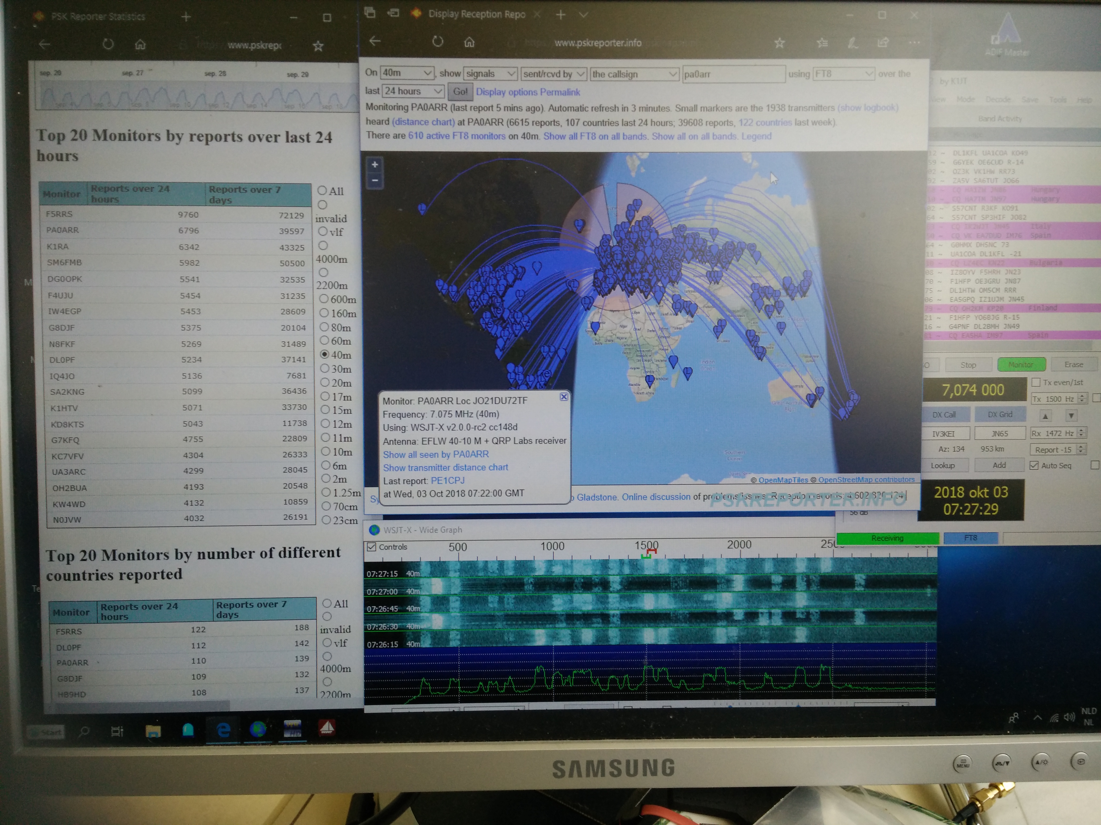
Great FT8 results on 40m by Ton PA0ARR
Ton PA0ARR sent me this screenshot of his FT8 reception report, using this receiver module on 40m, ranking on 03-Oct-2018, #2 in the world, only behind F5RRS's big antenna farm. Great job! CLICK for full-size image
RX module in 630m transceiver by Lou N2END
Lou writes:
"I thought I would show you a picture of my transceiver for 630 m which uses an RX module with polyphase network. On transmit, I have a homebrew SSB exciter and class E amplifier. This exciter-nonlinear amp combination works well for digital modes. For the receive front end, I use a bandpass filter made from 455 kHz IF filters. This is a simple design published by VK1SV on his website. VK1SV's filter page: http://people.physics.anu.edu.
The response of the filter looks like this after tuning it [see below left].
The receiver seems to work well down at these frequencies."


