|
|
QCX: a feature-packed, high performance, single-band 5W CW transceiver kit, with WSPR beacon and built-in alignment/test equipment. Available for 80, 60, 40, 30, 20 or 17m bands. It has rotary encoder synthesised tuning, VFO A/B/Split, Iambic keyer, CW decoder, and more... |

14-May-2020: The QCX kit has been replaced by the new QCX+ kit. Same circuit, same firmware, same functional operation - but physical improvements. See http://qrp-labs.com/qcxp for details.
The "QCX" is a 5W, single-band, high performance CW transceiver kit with WSPR beacon, and built-in alignment/test equipment. It is available for 80, 60, 40, 30, 20 or 17m bands. See below for the long list of features! This is a kit of parts that you assemble yourself. There are NO surface mount components to solder (two SMD ICs are already factory pre-soldered).
Please see QCX Frequently Asked Questions page for any queries you have. In case of any problems, please see the QCX trouble-shooting page.
Features
- Easy to build, single-board design, 10 x 8cm, all controls are board-mounted
- Professional quality double-sided, through-hole plated, silk-screen printed PCB
- Choice of single band, 80, 60, 40, 30, 20 or 17m
- Approximately 3-5W CW output (depending on supply voltage)
- 7-16V recommended supply voltage
- Class E power amplifier, transistors are bolted to the PCB as a heatsink, though heat dissipation is minimal
- 7-element Low Pass Filter ensures regulatory compliance
- CW envelope shaping to remove key clicks
- High performance receiver with at least 50dB of unwanted sideband cancellation
- 200Hz CW filter with no ringing
- Si5351A Synthesized VFO with rotary encoder tuning
- 16 x 2 blue backlight LCD screen
- Iambic keyer or straight key option included in the firmware
- Simple Digital Signal Processing assisted CW decoder, displayed real-time on-screen
- On-screen S-meter
- Full or semi QSK operation using fast solid-state transmit/receive switching
- Frequency presets, VFO A/B Split operation, RIT, configurable CW Offset
- Configurable sidetone frequency and volume
- Connectors: Power, 3.5mm keyer jack, 3.5mm stereo earphone jack, BNC RF output
- Onboard microswitch can be used as a simple straight Morse key
- Built-in test signal generator and alignment tools to complete simple set-up adjustments
- Built-in test equipment: voltmeter, RF power meter, frequency counter, signal generator
- Beacon mode, supporting automatic CW or WSPR operation
- GPS interface for reference frequency calibration and time-keeping (for WSPR beacon)
- CAT control serial data interface
- Optional 50W PA kit
Assembly and operating instructions
The assembly document includes circuit diagram and a detailed description of transceiver operation. Please download the correct assembly instructions for your PCB revision. The PCB revision is the number in the bottom right corner.
NOTE: PCB Rev 4 kits shipped after 12-Apr-2019 have four component changes. Make sure you have the correct manual version. There are four component value changes in these kits shipped after 12-Apr-2019, which are explained on page 7 of the latest 1.12 manual dated 20-Apr-2019.
DOWNLOADS:
- PCB Rev 5 Manual CLICK HERE (document revision 1.21, 12-May-2020)
- PCB Rev 4, Firmware 1.03 (kits shipped after 03-Dec-2019 Manual CLICK HERE (document revision 1.16, 02-Jan-2020)
- PCB Rev 4, Firmware 1.01 (kits shipped after 07-Oct-2019 Manual CLICK HERE (document revision 1.13, 07-Oct-2019)
- PCB Rev 4, kits shipped after 12-Apr-2019 Manual A4 format, CLICK HERE (document revision 1.12, 20-Apr-2019)
- PCB Rev 4 Manual A4 format, CLICK HERE; for Letter paper, choose scale to fit page when printing (document revision 1.11, 31-Oct-2018)
- PCB Rev 4 Manual RUSSIAN, CLICK HERE - translation by Andrey R1CF (THANKS!) (revision 1.11a, 21-Jan-2019)
- PCB Rev 4 Manual JAPANESE, CLICK HERE - translation by Shig JA1XRQ, see website here (THANKS!) (revision 1.11a, 05-Dec-2018)
- PCB Rev 3 Manual A4 format, CLICK HERE - for world except North America (document revision 1.10, 26-Jan-2018)
- PCB Rev 3 Manual Letter format, CLICK HERE - for North America (document revision 1.10, 26-Jan-2018)
- PCB Rev 3 Manual GERMAN, CLICK HERE - A4-format German translation contributed by Peter DL6DSA (THANKS!) (revision 1.10a, 10-Feb-2017)
- PCB Rev 1/2 Manual A4 format, CLICK HERE - for world except North America (document revision 1.08, 23-Oct-2017
- PCB Rev 1/2 Manual Letter format, CLICK HERE - for North America (document revision 1.08, 23-Oct-2017)
- PCB Rev 1/2 Manual GERMAN, CLICK HERE - A4-format German translation contributed by Peter DL6DSA (THANKS!) (revision 1.08, 23-Oct-2017)
- PCB Rev 1/2 Manual JAPANESE 3-parts: part-1 part-2 part-3 translation of sections 1-4, contributed by Shig JA1XRQ (THANKS!) See Shig's website for single doc (revision 1.08, 06-Nov-2017)
- PCB Rev 4 Hi-resolution (300dpi) circuit diagram/schematic, 4,375 x 2,279 pixels
- PCB Rev 3 Hi-resolution (300dpi) circuit diagram/schematic, 4,368 x 2,282 pixels
Firmware
There have been several firmware updates since the 21-Aug-2017 launch of this QCX CW transceiver kit. These provide enhancements and bug fixes. If you have an AVR programmer you can update your firmware using the on-board programming header. The firmware version history and more information are on this page (click!).
Operating manuals for firmware version 1.06 and above are a separate document and are also on the Firmware history page.
Modifications
CLICK HERE for a Modifications page, various improvements you can easily make to your QCX radio.
PCB Revisions
There have been a number of PCB revisions, these included minor changes which improved some aspect of the QCX or enabled new functionality.
Rev 1: Original version, August 2017
Rev 2: Minor changes
Rev 3: (26-Jan-2018)
1) Modification to improve contrast potentiometer adjustment; added R65 (3.3K) (described here).
2) Modification for unreliable microcontroller startup included as standard (described here).
3) Modification to prevent occasional PA instability; added R64 (10K) (described here).
Rev 4: (31-Oct-2018)
1) Changed C21 and C22 to 1uF (previously 10uF) to reduce click on Tx/Rx switchover
2) Kits shipped after 12-Apr-2019 changed R41 from 470 to 150 ohms; R42 from 1K to 1.2K; C31 from 1uF to 2.2uF; to improve key-shaping.
3) Kits shipped after 12-Apr-2019 also changed R21 from 7.5K to 10K to allow phase compensation for larger range of component tolerances.
Rev 5: (06-Jan-2020)
1) Removed components R49, R50 and C39; R53 changed from 1K to 3.3K; the components were not needed since AUDIO2 DC bias is 2.5V already
2) Added R49 (1K), R50 (270-ohm) and D7 (1N4148) which are to implement a serial port for the CAT control interface
Photographs
These photographs show the prototype kit, both with and without the LCD module plugged in. The powered-up kit shows the radio's Frequency Counter feature measuring the frequency generated by its Signal Generator feature.


Builders' enclosure photographs
A common question about the QCX transceiver, is about what case to use for it. There is not an official QRP Labs enclosure for the QCX. But many people are finding their own solutions to this question.
For photos and information about what some constructors have done about enclosing their QCX, visit the QCX builders' gallery page!
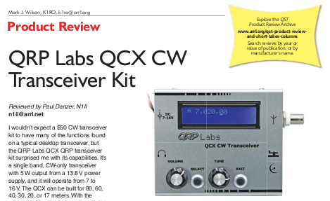
ARRL Review of QCX in August 2019 QST issue
Paul N1II reviewed the QCX transceiver in the August 2019 issue of the ARRL monthly publication QST. Quoted performance for QCX+ is expected to be equivalent to QCX, since there are no component changes and great attention has been given to PCB layout in both QCX and QCX+.
CLICK HERE to read the PDF (497K file)
Reproduced with the permission of the ARRL. Copyright ARRL.
Visit the ARRL website here.
Videos and reviews of QCX
The original QCX kit was originally designed for the RSGB Youths On The Air summer camp buildathon in August 2017. This RSGB YOTA Vlog video, shot at QRP Labs booth at Friedrichshafen 2017.
For more videos and reviews please see the QCX videos page!
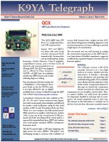
K9YA Telegraph, March 2018 edition, review by Philip K9PL
The K9YA Telegraph's March issue has an article on the QCX by Philip K9PL, sub-titled "QRP Labs Moves the Goalposts". Philip concludes his 3-page article: "...the QCX behaves like a monoband, QRP slice out of a QRO high-end rig with deep, deep menus - very innovative and a joy to operate.
The K9YA Telegraph is a free monthly Ham Radio eZine, see http://www.k9ya.org/ for details.
Philip K9PL has provided a PDF of the article with permission to reproduce it on the QRP Labs website. CLICK HERE to read it!
Common Issues
The following issues have arisen more than once, and have the solutions indicated.
| Issue | Solution |
| Microprocessor does not boot up at power-up, requires switch-off/switch-on again to power up properly | See modification here |
| Power Amplifier instability results in low or unstable power output, or high current draw, or blown MPS2907 | See modification here |
| LCD contrast fluctuates on transmit | Check for LCD module frame short to L2, see here for details |
| Low output power on 20m (or other band) | LPF inductance is probably too high, resulting in attenuation at the transmit frequency. Remove turns one at a time from LPF inductors L1, L2, L3 |
| No power output at all | Check continuity through L1, L2, L3 and other inductors L4 and T1, as advised in the manual. Probably one or more have not properly burnt off the enamel so there is no electrical connection. |
More troubleshooting
- There is an extensive QCX troubleshooting guide, click here
- An excellent article on troubleshooting 60 QCX-series kits, by Ron WA7GIL, see here
- There is a detailed video about QCX troubleshooting, click here
Phase noise measurements
For a detailed page about phase noise measurement techniques and the measurements on the QCX in particular, CLICK HERE.
The transmitter output phase noise measured was within 1dB of the -135 dBc/Hz at 10 kHz and 50 kHz spacing measured by ARRL in their QST review (see above). This level is considered GOOD. No improvements were found to get better phase noise performance from the QCX.
Performance measurements by Ed WA4MZS
Ed made some interesting measurements of his 40m QCX serial number 354 (see also builders' photos page).
- Power supply = 13.8 VDC
- Current draw (receive) = 123 mA
- Current draw (transmit) = 514 mA
- Transmitter output (50Ω load) @ 7.020 MHz = 4.0 watts
- Receiver MDS @ 7.020 MHz = -121 dBm (0.2 µV)
- Reference frequency = 27.004345 MHz
- Transmitter frequency (display 7.020 MHz) = 7.0200003 MHz
- Transmitter 2nd harmonic (14.040 MHz) = -48.74 dBc
Spectrum analyser close-in and wide screenshots:


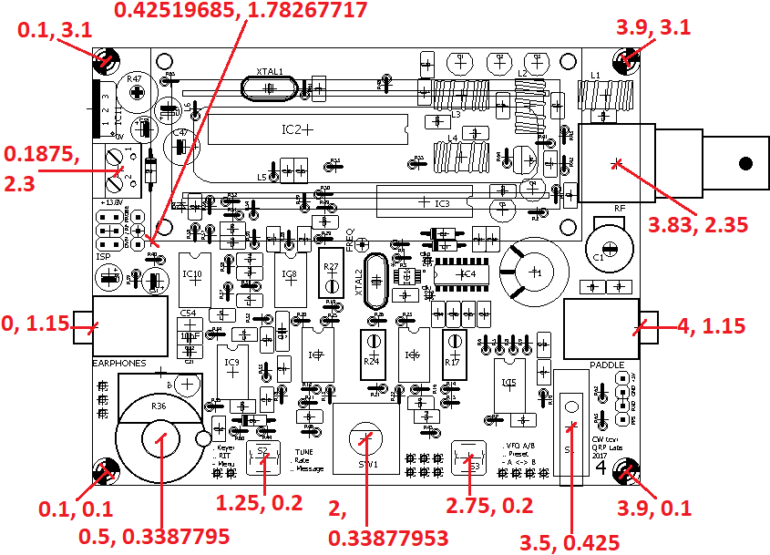
Board dimensions
The following diagram shows some dimensions of the QCX PCB. Important notes:
- All dimensions indicated are in inches. Multiply by 25.4 to get mm
- The PCB size is 4.0 x 3.2 inches exactly
- The coordinates are indicated as X, Y in inches, relative to the 0, 0 origin which is the bottom left corner of the PCB
- The coordinates of the gain potentiometer, tuning control, and the two buttons are all the center points of the control shafts
- The coordinates of the PCB mounting holes in the corners are the center points of the drill holes
- The coordinates of the BNC socket, 3.5mm jack sockets (audio out, paddle in), Power connector and microswitch (straight Morse key) are all the coordinates of the Eagle CAD library component origin, and are as shown by the end of the line mark on the diagram.
- The coordinates of the LCD Module are the bottom left corner origin of the module, as shown. Please refer to the information on the LCD module below this diagram.
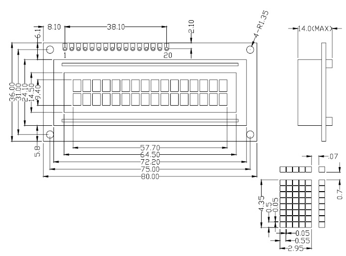
Specific notes about the LCD module:
- The dimensions on this LCD module diagram (below) are in mm. Divide by 25.4 to get inches
- The coordinates (in inches) of the LCD module in the above QCX PCB diagram refer to the bottom left hand corner of the LCD module
- The LCD module is separated from the main QCX PCB in the vertical direction, by four 12mm nylon hex spacers installed at the corners
- The LCD module PCB size is 80 x 36mm
- The four corner holes are centered 2.5mm in from each corner of the LCD module
- Do NOT trust the dimensions in the following diagram, for the HEIGHT of the module (cross-section at upper right of the diagram) and for the size of the black metal cover-plate for the LCD glass. These dimensions are known to vary slightly from manufacturer to manufacturer. So if you require exact measurements for these parameters you should verify them with your own measurements. The other dimensions (hole location, 80 x 36mm board size) are always standard.