The Ultimate QRSS Transmitter Kit was available in 30, 40, 80 and 160m versions. The kit is now retired and the pages here are provided for information purposes only.
Instructions
DOWNLOAD KIT INSTRUCTIONS BY CLICKING HERE - printed instructions are not supplied with the kit.
SPANISH KIT INSTRUCTIONS v1.04 CLICK HERE - many thanks to Luis EA2COA who generously spent a lot of his time translating the instructions into Spanish.
Firmware Version History - please CLICK HERE
|
The kit supports the following modes: - QRSS mode (plain on/off keyed slow CW) - FSK/CW mode (frequency shift keyed slow CW) - DFCW mode (dual frequency CW) - WSPR mode (Weak Signal Propagation Reporter) - Slow-Hellschreiber (frequency shifted slow-Hell) - Full-speed Hellshreiber - Half-speed ("DX") Hellshreiber - CW (plain CW) - Customisable FSK patterns |
Other features: - 24-character LCD + two-button user interface - User-programmable (callsign, message, speed, FSK, mode, etc.), settings stored in EEPROM - GPS interface, for locking the frequency in slow-speed modes - On-chip generation of WSPR encoded message (no PC required) - WSPR maidenhead locator can be generated from GPS-derived latitude/longitude - Selectable “frame” size, for stacked QRSS reception - Plain CW callsign identifier at selectable interval - Produces 150mW RF output, or AF output for driving an SSB transceiver - Higher output power by additional PA transistor and/or higher PA supply voltage |
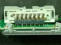
The kit contains the PCB, LCD, programmed microcontroller and all board-mounted components. Download the instruction manual using the link above. The PCB is quite compact and moderate care is required in the construction. A rich array of functionality is provided by the design; please read the instruction manual to understand the facilities provided. Builder modifications will be shown on this page as they are developed!
Note for WSPR users: the 30m kit has a 10.140MHz crystal which is suitable for either the QRSS sub-band or the WSPR frequency. Therefore on 30m the kit can be used as a standalone WSPR transmitter. On other bands you may need to supply a suitable crystal for the WSPR frequency on that band. Alternatively you could use this kit in the AF output mode, fed into a conventional SSB transmitter set to the frequency of your choice.
Kit photos (click for larger versions):


Updates
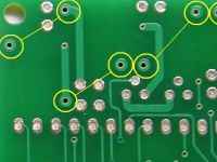 |
Solder mask errorThe PCB has an error, where solder-mask is incorrectly applied to the toroid pads. This is easy to scrape off with a knife or screw-driver blade. |
 |
GPS NotesHere are some notes about which GPS module to use, what to consider when purchasing a GPS module, and the method of frequency stabilisation used in the kit. |
 |
Right-angled LCD mountingJohn VK6JY sent photos and an explanation of how to connect the LCD at right-angles to the PCB, convenient for a front-panel display for example. |
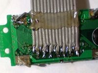 |
LCD connection method of Mike G8NXDMike G8NXD had problems splaying the LCD pins to connect wires, and describes his solution. |
 |
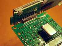
LCD connection method of David G8OQWDavid G8OQW describes an elegant display connection solution using a ribbon cable connector. |
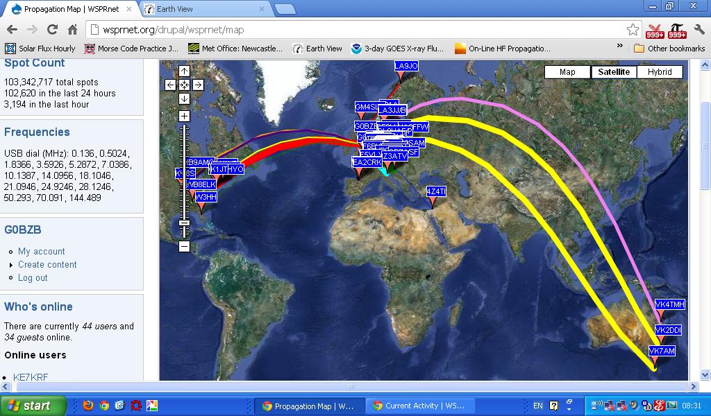 |
One night's 30m WSPR operating, by Tony G0BZBJust one night of operating 30m WSPR using the bare kit gave plenty of WSPR hits for Tony G0BZB (09-Sep-2012). |
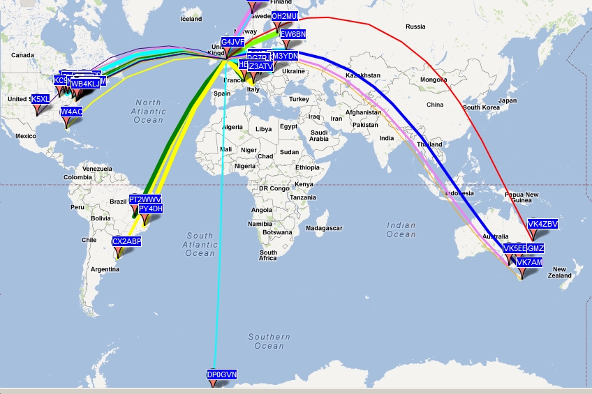 |
One night's 20m WSPR operating, by Philip G4JVFPhilip ordered a custom-made 20m crystal from QuartzlabUK (costing more than the kit price!) with the kit operating into a 132-foot Windom antenna, and was rewarded with WSPR spots worldwide over a 24-hour period (20-Sep-2012). |
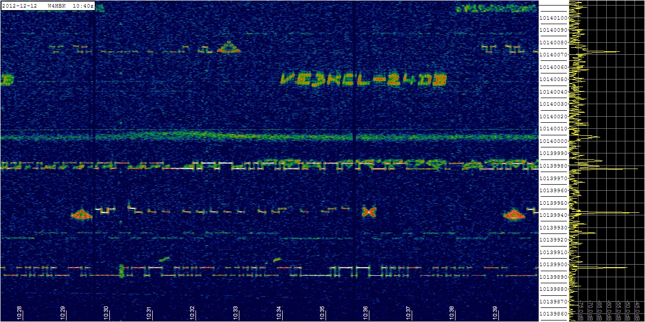 |
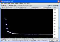
WSPR and Hell, by David VE3KCL in TorontoDavid VE3KCL operates from Toronto FN04 and the screenshot (left) is W4HBK's grabber at 1,700km distance. David uses two BS170's with heatsink, and got 800mW at 12V supply, subsequently lowering it to 250mW. He uses WSPR and Hellschreiber to a G5RV antenna. |
Kit version history:
| Version | Date | Features |
| v1.00 | 19.May.2012 | - Original kit firmware version |
| v1.01 | 23.Jun.2012 | - Bug fix: to the “Frame” parameter (beacon can sometimes stop transmitting after 1 hour) - Lowered the minimum frequency from 1,000,000 Hz to 450,000 Hz |
| v1.02 | 22.Jul.2012 | - Bug fix: correcting the operation of the on/off keying in some modes |
| v1.03 | 31.Jul.2012 | - Bug fix (cosmetic only): baud rate setting so it only accepts numeric characters - Bug fix (cosmetic only): “frame” mode, waiting display was incorrect - Improved GPS stabilisation algorithm - Added ability to use different cursor types on the display |
| v1.04 | 07.Aug.2012 | - Bug fix: correcting the conversion of GPS latitude and longitude to Maidenhead locator |
| v1.05 | 28.Aug.2012 | - Bug fix: When “Start” is non-zero, it always transmitted one frame on the hour - Removed the restriction on zero “FSK (Hz)” parameter - Output a high signal on connector F0 when the GPS is enabled and the frequency is locked - Now a space character in a custom message turns off the carrier - New TEST2 mode cycles the frequency range in 128 frequency steps. |
| v1.06 | 23.Sep.2012 | - New "Reset to factory" feature - Output a high signal on connector pin F2 while transmitting a frame. |
| v1.07 | 12.Oct.2012 | - Ignore any invalidly decoded GPS locator (no not write to EEPROM). - Bug fix: rare Latitude/Longitude to Maidenhead locator conversion problem. |
| v1.08 | 01.Jul.2013 | - Bug fix: after GPS fix, waiting time might not be recalculated causing missed cycles |