|
|
This relay-switched LPF board kit can have up to five additional LPF's plugged in, permitting the Ultimate3 and Ultimate3S QRSS/WSPR kits to sequence between 6 bands (including the LPF on the main U3 board). The board size is 80 x 37mm, the same as the U3, so the boards stack together using four 25mm hex spacers. The plug-in LPF modules are available separately, click here. |

The kit can also be used with your homebrew radio projects!
To order the kit, CLICK HERE for the product page at QRP Labs.
Assembly instructions
Assembly instruction manual for PCB Revision 5 (CHECK the revision printed on your PCB! Other versions, see below!)
FRENCH translation of the PCB rev 5 manual (thanks Michel ON4LAU for the translation)
More documents
Assembly instruction manual for PCB Revision 4 (the PCB has a "Rev 4" label printed on the right hand side).
RUSSIAN translation of the PCB rev 4 manual (thanks Andrey R1CAD for the translation!).
Assembly instruction manual for PCB Revision 2 and 3 (the PCB has a "Rev 2" or "Rev 3" label printed on the right hand side).
JAPANESE translation of the PCB rev 2/3 manual (thanks Toru JG1EIQ. See also his U3 photos here).
Assembly instruction manual for PCB Revision 1 kits shipped from 07-Feb-2014 onwards.
Assembly instruction manual for PCB Revision 1 kits shipped prior to 07-Feb-2014.
To order the kit, CLICK HERE for the product page at QRP Labs.
Kit relays, supply information
Note that the relays used in this kit are purchased from a surplus dealer. At the time when designing the kit (around 2014), I needed DPDT style relays with 5V coils, low enough coil current to drive directly from a microcontroller I/O pin (they are 28mA), and with very small size so that they could fit the physical constraints imposed by the existing kit family. At the same time I needed low cost! The only way to achieve this was to use these surplus relays that I found. In this regard the relay-switched LPF kit is unique among all other QRP Labs kits components which use only brand new components.
The relays used in the kits are surplus which in most cases means that they are leftovers unused from a manufacturing run, which may have been in storage for some time; in a few cases they may be recovered from PCB assemblies, so may show traces of used solder or other residue. Do not worry about this. Before deciding to use these relays in the kit I carefully tested 50 samples and all performed very well. The relays are a high quality type, manufactured by Panasonic. At the time of writing (August 2020) we have sold over 25,000 of these relays (mostly in the relay-switched filter kit, but also as individual relays for use in projects like the Clock kit). The quality and feedback has been very good, with very few failures; certainly this part does not have a higher failure rate than any other component we use.
Relay driver for Raspberry Pi and other systems
Some people wish to interface this relay kit with 3.3V systems such as the Raspberry Pi, or systems which cannot support the 28mA relay current from processor I/O pins directly. This relay driver is suitable for such cases. Read more here...
Kit photos
The photos below show the relay-switched LPF board plugged into the back of the U3/U3S kit. Note that my photos below show NO additional LPF's plugged in (as I only had one built LPF at the time of those photos).


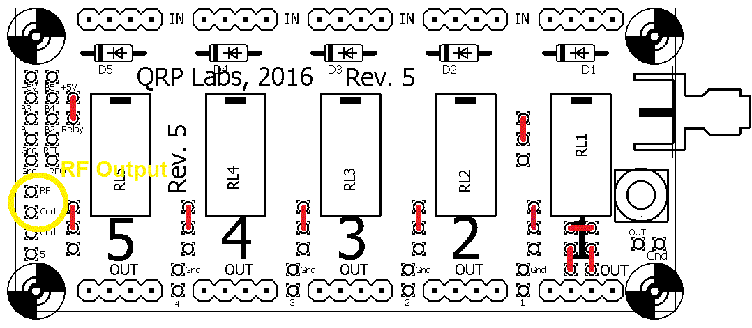
Using the Rev. 5 relay-switched LPF kit to switch Band Pass Filters
QRP Labs Band Pass Filter kits have the same pinout and footprint as the Low Pass Filter kits, so they also fit the relay-switched filter kit. Use Band Pass filter kits only for receiver input filtering (they should not be used at a transmitter output). In the standard configuration described in the assembly manual, the LPF kit inserted on the right (in position 1) is ALWAYS in-circuit and should be the filter for the highest frequency band installed. However, this is not suitable for when you wish to use the kit to switch band pass filters.
To switch band pass filters, use the jumper configuration shown below.
Note that the output SMA connector(s) on the right side of the board are connected permanently to the final (position 1) filter output. Therefore you cannot use them as the output, when using the board for Band Pass filter kit switching. In this case you should take the RF output from the connections circled in yellow, in the diagram. The RF input is the RFI pin of the 2 x 5-pin header on the left of the board (same as in the Low Pass Filter kit usage). An alternative is to cut the track from the SMA connector center pins and add a wire to connect it to the common bus track that runs horizontally across the board, finishing at the "RF" pad circled in yellow.
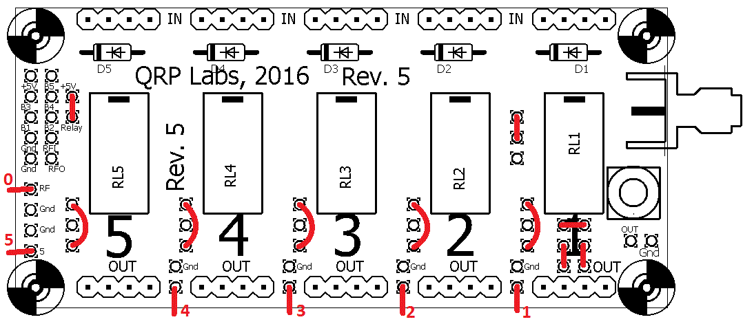
Using the Rev. 5 relay-switched LPF kit with 6 separate antenna outputs
The relay-switched LPF kit can be used with a common RF output, which is the default connection described in the manual. However it can also allow the relays to switch between up to 6 different outputs. This could be used to select different antennas, for example. It could allow antenna comparison experiments, or the use of different antennas for matching different bands.
The jumper configuration below shows the kit used to select between 6 different outputs. The output of each LPF is routed to a different pad on the board. The outputs are labelled 0 to 5 in the diagram. Note that relay 0 is the one on the main Ultimate3/3S kit PCB (when the relay board is in use with the U3/U3S kits).