Why this article?
Because, the topic causes endless confusion. It pops up, seemingly regularly, on the QRP Labs discussion forum (and elsewhere). People misunderstand how to use the internal RF Power meter in the QCX CW transceiver kit. Then there are the three possible measurements that can be taken (Peak voltage, Peak-to-peak voltage, and RMS Voltage). And the calculation from the measured voltage to the RF Power. Plenty of people are ambiguous about which measurement they are referring to, then typos are introduced, references to other web pages or discussion threads where errors were also introduced, and carelessness abounds, and before long the topic just got even more confusing than it already was. Hence this article, let's lay the topic to rest once and for all and if there are any errors or omissions, please let me know and I can correct them.
Does it matter?
Not very much, no. Certainly not as much as most people seem to think. We commonly refer to power in watts. Sometimes in dBm (decibels relative to 1 milliwatt). More on dBm vs Watts, below. dBm are what really matters in terms of how well people will hear you. dBm are linearly related to S-meter points on the radio receiver (signal strength, or how well people hear you). The relationship between power and S-meter readings is logarithmic. Roughly speaking, to gain 1 S-point in signal strength, requires quadruple power output. The difference in S-meter reading between 4W and 5W is rather small. Under 1dB, Which is to day, about 1/5th of an S point.
Still, people care. I care, you care. We want MORE WATTS. And that's OK.
Abundant inaccuracies
The relationship between power and watts involves squaring the voltage. Any inaccuracies in the measurement or the equipment or the setup get magnified when expressed in watts. There's plenty of opportunity for error. Lots of error... You do well to remember two things:
First: is Segal's law: "A man with a watch knows what time it is. A man with two watches is never sure." And though Segal was talking about time, the same evidently applies to RF Power measurements.
Second: is what I said above. It doesn't really MATTER all that much, anyway. Often relative power measurements are more useful than absolute measurements.
Pre-requisites
Common misunderstandings are everywhere. Look, to start with, you need to measure power across a known resistive load. A 50-ohm dummy load. Much like the QRP Labs 50-ohm dummy load kit ;-) Don't be tempted to try any measurements with anything else. Remember what I said, about abundant inaccuracies? So if you have an antenna connected, forget it. Even if you think that piece of wet string is a resonant dipole and is all well matched and the SWR is well, your SWR meter says it is better than 1.3 : 1 so yes it really must be, mustn't it... NO, just please, forget it... the antenna will magnify any errors in the measurement. You can say that you are producing some power, and it is in the right ballpark, or at least the right stadium grounds... but not a lot else.
The next thing you need is a sinusoidal wave. The "RF Power" you are looking for, is the power dissipation in a 50-ohm resistive load. Calculations involving the conversion of Vpeak-peak to RMS, and RF Power, all assume a sinusoidal shape to your waveform. Most RF power meters will operate by measuring voltages then converting this to RF power using formulas - which assume a sinewave, and assume a 50-ohm resistive load. If you have an RF Power meter which actually measures heat in a load, then lucky you.
So don't try to measure RF power directly at the output of a Class-E power amplifier like the QCX transceiver has. The waveform isn't sinusoidal. The calculations are therefore invalid. Don't try to measure the power half-way along the Low Pass Filter either - since the impedance at this point is not likely to be 50-ohms, again the calculations are invalid. Only measure power across a good 50-ohm dummy load!
Again to summarise:
1) 50-ohm dummy load, not an antenna, even if you think it is accurately tuned!
2) Only measure sinewaves!
What is the difference between Vpeak, Vpeak-peak and Vrms?
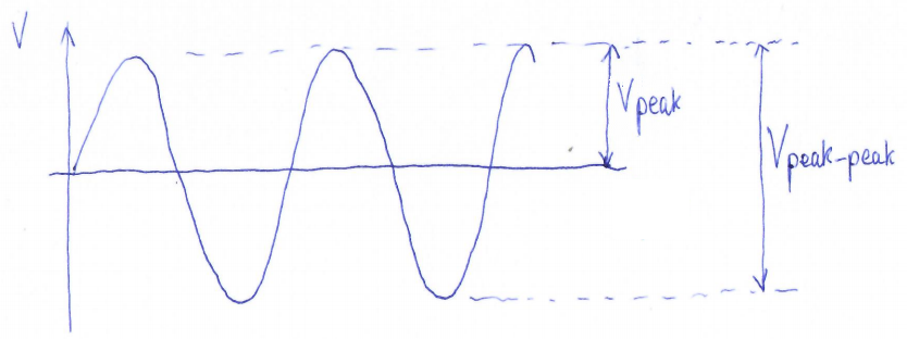
An oscilloscope shows you the actual waveform. (Or does it? See more below). Refer to my amazing artwork, the sketch below. This shows a sinewave, much as we might see on an oscilloscope, which is symmetrical about zero, the horizontal line in the middle.
- Vpeak-peak (the peak to peak voltage) is the voltage difference between the positive going and negative going peaks of the sinewave.
- Vpeak (the peak voltage) is the voltage difference between the zero center-line, and the positive peak (or equivalently, the negative peak).
In fact, Vpeak is half Vpeak-peak. And Vpeak-peak is 2 x Vpeak.
What of Vrms?
Refer to my next sketch:
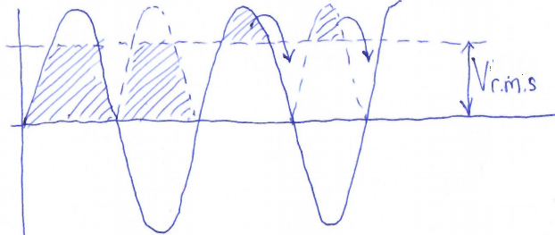
Vrms means Voltage "root mean squared". See https://en.wikipedia.org/wiki/Root_mean_square. If we took an infinite series of voltage measurements along the sinewave, and squared them, and then took their average, and then square-rooted the average, we'd end up with Vrms. However we don't need to do that. For a perfect sinewave, it is possible (but I'm not going to stretch my feeble brain to this right now) to prove mathematically that
Vrms = 0.707 x Vpeak.
0.707 is 1 / sqrt (2). Another way of looking at it, which I find convenient... is that we actually want the area under the curve, to calculate the power. So imagine the negative parts of the sinewave being flipped up (since the resistive load doesn't care if the voltage is negative or positive with respect to ground, only the magnitude of the dfifference); then we want to calculate the average voltage for power calculation reasons. Imagine we want the shaded area under the sinewave, and then the top peak piece of each sinewave half, above the Vrms dotted line in the diagram above, gets flipped over and exactly fits in the corresponding valley. So effectively with Vrms we calculate the area under the sinewave. Calculus (integration) proves the 0.707 factor but my head hurts enough already thank you.
Power = Voltage x Current.
We don't want to worry about Current so we remember Ohm's law which is Voltage = Current x Resistance; then Current = Voltage / Resistance
So Power = Voltage ^ 2 / Resistance
(Voltage ^ 2 means "Voltage-squared", i.e. Voltage * Voltage). Here, the voltage we are referring to, is the Vrms (Root Means Square, RMS voltage). Resistance is 50-ohms, which is the reference load we use in amateur radio by convention. Therefore:
Power = Vrms ^ 2 / 50
One can also put in the formulas Vrms = 0.707 x Vpeak, and Vpeak-peak = 2 x Vpeak, in order to get the equivalent Power formulas in terms of Vpeak and Vpeak-peak:
Power = Vpeak ^ 2 / 100
Power = Vpeak-peak ^ 2 / 400
That's it! Three easy formulas. Understand the voltage you measured. Is it peak-peak? Or peak? Or rms? And then square it and use the appropriate division ratio.
dBm vs Watts
Power is quoted sometimes in Watts, and sometimes in dBm.
dBm is the dB ratio between the power in question, and 1mW. So 1mW is nominally 0dBm. The formula for converting Watts to dBm is:
Power(dBm) = 10 x Log10 (Power / 1mW)
Where Log10 is the logarithm base 10.
So for example, our common QRP "gallon" is conventionally defined as 5W (that is, QRP power means 5W and under).
Power in dBm is 10 x Log10 (5W / 1mW)
= 10 x Log10 (5000)
= 10 x 3.70
= +37dBm
You usually see power measurements in dBm quoted with a + or - sign in front. This is because the sign matters! Any power smaller than 1mW will have a negative value when expressed in dBm. Whereas a power expressed in Watts can only ever be a positive value so it is not necessary to mention the sign. For example, a power level of 0.1mW, is expressed as "-10dBm".
RF Power measurement using a DVM
Not just any DVM, mind you! Your DVM needs to have an RMS function. Then you can directly read Vrms, square it, and divide by 50 to get the power. BUT, how much do you trust the DVM's RMS function? How accurate is it at radio frequencies? Do you know?
 RF Power measurement using an RF detector
An RF detector often consists of a simple diode and capacitor to detect and "rectify" the RF. That results, viewing things simplistically, in Vpeak. The QCX transceiver includes an RF detector of this type. The QRP Labs 50-ohm dummy load kit also includes this type of RF detector (just the simple addition of a diode and a capacitor). The resulting rectified RF is a DC voltage and can be measured with any voltmeter (DVM).
Unfortunately there are a lot of problems with this method, which give rise to inaccuracies, whose magnitude escalates (see above).
The graph (right) shows measurement of a QRP Labs 50-ohm dummy load, the DVM voltage reading (DC) corresponding to RF Power (horizontal axis). Problems arise because the diode has a certain voltage drop (typically around 0.6V). Diodes all have a different characteristic from one device to the next, so it's impossible to provide one graph that will be accurate for everyone. Additionally, the DVM input will imply some loading that can also affect the result.
Nevertheless many power meters work this way. Just remember, HOW ACCURATE is it? Do you know?
RF Power measurement using the RF detector in the QCX
 The QCX transceiver includes an RF detector and a Power measurement menu. The detector is a simple diode and capacitor, as mentioned above. It's not highly accurate, due to all the reasons mentioned in the preceding section. It's a reasonable indication only. A ballpark measurement. The QCX firmware measures the peak voltage and does its own internal calculation of RF power, accounting (somewhat) for the diode voltage drop.
If the RF power measurement function is used, connect the center pin of the 3-pin "DVM/Power meter" header to the RF output, at the BNC connector (the output of the LPF).
Be very careful not to accidentally touch any wires to any other nearby pins such as the 2x3-pin In-Circuit-Programming header... the voltages can easily kill the ATmega328 microcontroller and this is a quite common cause of failure.
There are several important points to note about using the RF detector in the QCX for RF power measurement:
- I have to say this again, as it is so important: do NOT expect the results to be highly accurate! Just take them with a pinch of salt. This is not a highly accurate way of measuring RF power!
- As above, make sure you have a 50-ohm dummy load connected to the output of the QCX! The measurement is meaningless otherwise.
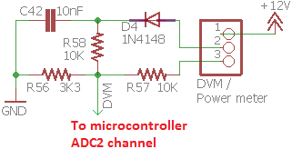
- The input of this RF detector should only be connected to signals having no DC bias. In other words, AC-coupled i.e. a coupling capacitor is in circuit. In the QCX, this is the case at the RF output because of capacitor C29 (refer to schematic). This means the signal is correctly referenced to ground. The center-line of the sinewave, is the same as ground. No DC bias!
- The scaling of the resistors R56 and R58, which form a potential divider, is such that the maximum reading from this RF power meter is 5.2W. If you see 5.2W on the screen, it means "anything from 5.2W and up". You maxed out the processor's Analog to Digital Converter input.
- Do NOT connect the RF power meter to any other place, than the 50-ohm dummy load / RF Power output of the transceiver. Results will be meaningless!
- Again: do NOT connect the RF power meter to the junction points of any of the inductors. The impedance here is not exactly 50-ohms and the reading will be wildly inaccurate. Do NOT connect the RF power meter to the drains of the BS170s either! Here the impedance is neither exactly 50-ohms, NOR is it free from DC bias! So the results are again meaningless.
So in conclusion:
- Always use a 50-ohm dummy load
- Only measure power across the 50-ohm dummy load
- Don't put too much faith (or hardly any at all) in the accuracy of the reading
RF Power measurement using an Oscilloscope
An oscilloscope can be one of the best ways to measure RF power, because you can directly see the waveform on the screen, and make sure it is sinusoidal; and you can directly measure the Vpeak-peak. Modern Digital Storage Oscilloscopes (DSO) include a function for measuring and displaying Vpeak-peak on screen. That's very convenient.
Be sure to use a x10 oscilloscope probe, to avoid adding capacitative and inductive loads in parallel with the 50-ohm dummy load that can distort the measurement. The x10 probe needs to be accurately compensated. Compensation involves using the test output of the oscilloscope (normally 1kHz, 1V squarewave) and adjusting the trimmer capacitor on the 'scope probe until the squarewave is really perfectly square without any overshoot or rounded edges. Refer to your oscilloscope's manual.
The voltage rating of your oscilloscope/probe input should be easily capable of handling QRP power levels. A 5W QRP power output into 50-ohms is a 45V peak-peak sinewave which is not an enormous voltage by any means. So direct connection of the probe to the dummy load is fine.
Things to be aware of:
- Again, you have GOT to use a good 50-ohm dummy load
- To obtain accurate measurements your x10 oscilloscope probe should be accurately compensated
- Your oscilloscope should be accurately calibrated - many modern DSOs include a self-calibration function
- Know your oscilloscope... It isn't impossible to mis-use a digital oscilloscope and obtain misleading results. If you adjust the horizontal timebase to show several complete RF cycles on the screen this should be a quite reasonable way to be sure all is well.
- Make sure your oscilloscope has an adequate bandwidth to properly display the operating frequency accurately; there are many inexpensive eBay/AliExpress/etc oscilloscopes with small LCD screens, having bandwidths of not more than a MHz or two. If you connect these to your 40m QCX (7MHz), you will see something but don't expect it to be accurate.
The bandwidth point is an important one! The bandwidth is defined as the point where the input amplifiers of the oscilloscope exhibit a 3dB (voltage) loss. At this point the measured amplitude is 70.7% of the real amplitude. Therefore do not assume that if you have a 10MHz oscilloscope, you can accurately measure a 30m band (10MHz) transmitter. The oscilloscope bandwidth must be at least twice the operating frequency, some would say even more than that. Likewise, to make any reasonable decision about whether the signal is sinusoidal or not, requires an oscilloscope having a bandwidth 5 or 10x the operating frequency, since the most likely distortions are harmonics.
RF Power measurement using a Spectrum Analyzer
If you are lucky enough to own a real Spectrum Analyzer then this is another great way to measure RF Power.
 BUT... be very careful! The input of your spectrum analyzer, while it does say 50-ohms, is not designed to measure large levels of power! Not even 5W! The writing on next to the RF input connector of my old Advantest R3361C says "+25dBm MAX". Well, +25dBm is only 0.3W.
Therefore to be able to use the spectrum analyzer to measure power, you must use an attenuator! The attenuator must be capable of handling the power level you intend to measure, and it must have sufficient attenuation that at its output the signal level does not exceed +25dBm. For example, for our 5W QRP Power, the attenuator must be at least 12dB in my case (+37dBm - +25dBm = 12dB).
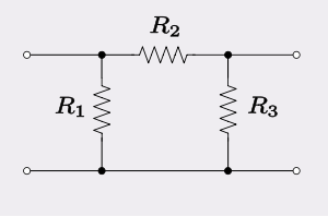
A good attenuator is a pi-network type see https://en.wikipedia.org/wiki/%CE%A0_pad
When using a 50-ohm input attenuator and a 50-ohm input spectrum analyzer, you do NOT need to use a 50-ohm dummy load at the output of the transmitter. The attenuator with the spectrum analyzer at its other end, is playing the part of 50-ohm load.
There are numerous websites for calculating resistor values for a Pi network for any desired level of attenuation. Google will find them for you. I found https://chemandy.com/calculators/matching-pi-attenuator-calculator.htm first. But there are many, and the results are all the same.
When building a Pi-Network attenuator take note of the following:
- Calculate for 50-ohm input and output impedance
- Use resistors with adequate wattage rating to cope with the expected power levels
- Be sure to use film resistors, NOT wirewound types, the latter have inductance and the load will no longer be purely resistive!
- If you cannot find the exact resistor values, you can build up equivalent values using parallel or series combination of commonly found resistance values.
I actually did recently build a 20dB 5W attenuator (December 2019) and here are the photos to prove it:


Unfortunately I wasn't happy with the results! If I connect a 50-ohm dummy load to my transmitter (QCX), and look at Vpeak-peak on the oscilloscope; then if I change the 50-ohm dummy load to this 20dB 5W attenuator, and look at the (transmitter output) Vpeak-peak on the oscilloscope. I should see the same Vpeak-peak as before; this is because the 20dB attenuator functions as the 50-ohm load. Unfortunately, I did NOT see the same Vpeak-peak and the difference was sufficient to be alarming; this requires further investigation but I suspect is due to some of the resistors in the dummy load being wirewound and therefore presenting some unwanted reactance in addition to the desired resistance.
The poor-man's attenuator
 A quick-and-dirty attenuator, is just a 1K resistor in series. So the set-up is: 50-ohm dummy load connected to the output of the transmitter (which was not, in this case, a QCX). Then a 1K resistor in series to the spectrum analyzer. The resistor does not have to be high wattage as it will not dissipate much power (at QRP 5W). This resistor plus the spectrum analyzer's 50-ohm input resistance, make 1050 ohms. In parallel with the dummy load, the result is 47.7-ohms. It's close enough to 50-ohms that it does not too badly affect the performance of the transmitter power amplifier or the subsequent Low Pass Filter. It is then possible to calculate (using potential divider arithmetic) that the simple 1K resistor effectively acts as a 26dB attenuator.
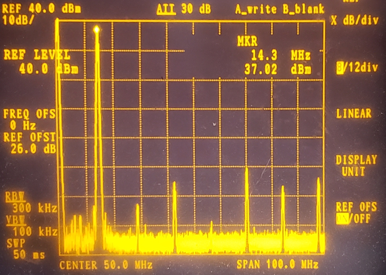
Now it's possible to obtain beautiful spectrum analyzer traces showing the harmonic levels and the power level of the fundamental on 14MHz. I could set up the "Reference Offset" of the spectrum analyzer to +26dBm such that the cursor measurement directly shows the power output. Here, +37.02dBm. Really close to exactly 5W.
This transmitter shows really low levels of 2nd, 3rd and 4th harmonics. Higher order harmonics tend to be a bit higher, this is because in my rough test set-up there isn't much attention to board layout or shielding so at VHF, signals leak all over the place.
BEST of all... when I measured the same transmitter, using the oscilloscope approach (50-ohm dummy load and peak-peak voltage on the oscilloscope), it also gave almost exactly the same measurement, 5W. So I was very pleased that the self-calibration function of the oscilloscope (Siglent SDS 1202X-E, prize from corporate sponsor of the homebrew heroes award 2019), and the self-calibration feature of the spectrum analyzer, and the calculation of my "poor man's attenuator", had all resulted in a consistent agreement between the oscilloscope and the spectrum analyzer. In clear violation of Segal's law (sorry OM).
CALIBRATION
Finally, remember this very VERY important point: Any measurement is only as good as the calibration of your equipment. This applies to everything: DVM, Oscilloscope, RF Power meter, Spectrum Analyzer. Even if the specification of a particular piece of equipment says "1%" (for example), you have to bear in mind, and QUESTION, how reliable is that specification? Is your equipment from a known, high quality manufacturer? Or, did you buy it for $5 from eBay with no instructions or heritage? Even if it is a reputable, calibrated instrument... when? Calibration drifts over time.
So... it's hard to be sure, whether you have an accurate result or not. If your instrument has a self-calibrating function, all the better. Still, you wonder, how accurate is that self-calibrating function? Anyway, run it. If you are using x10 oscilloscope probes, make sure they are accurately compensated.
In my case, it certainly did help inspire confidence when I was able to obtain consistent results between two different instruments (Advantest R3361C spectrum analyzer, and Siglent SDS 1202X-E oscilloscope).
Or... what about building your own calibration signal source? This is not as hard as it sounds. Recently, I had a lot of fun building a 7MHz calibration source in an Altoids tin. It produces a 7MHz sinewave with 0dBm and -60dBm outputs on BNC connectors. 0dBm is 1 milliwatt, and -60dBm is 1 nanowatt. I made a YouTube video about it for the QRP Labs YouTube channel, which you can see below or click here: https://www.youtube.com/watch?v=732ESoul088.
Again I was VERY pleased with the result - my Advantest R3361C Spectrum analyzer and my other oscilliscope (Owon XDS3102A 100MHz DSO) both closely agreed on the 0dBm output level of 1mW. The -60dBm output is too small to measure on an oscilloscope but the spectrum analyzer also thought it was quite close to -60dBm (within 1dB).
Conclusion
The concepts of RF Power measurement were discussed. Several methods of RF Power measurement were described (DVM, RF detectors, QCX RF Power meter, Oscilloscope, Spectrum analyzer).
I have to stress again that accurate measurements depend on accurately calibrated, reliable, good quality equipment. It can be very helpful to calibrate two instruments and compare the results - that really raises confidence levels in the measurement. It can also be useful to build a calibration signal source to use to calibrate your equipment.
And in the end... if you do NOT have accurate results... remember, practically speaking on air, the difference is very small. Your equipment can still be used nicely for ballpark and for relative measurements of RF power level, which are sufficient in many cases.