A batch of 1,000 QLG1 GPS module kits prepared in 2018 contains a defective YIC GPS RF module. The error on the part of the RF module manufacturer (YIC) consists of an incorrect firmware version that does not enable the 1pps output. 182 of these defective kits were shipped to customers before we realized the problem. The steps listed here explain how to "repair" a defective QLG1 GPS by re-flashing the RF module GPS engine chip firmware with a correct version supplied by YIC.
All of this procedure was developed by Garland K6GOG and we are very grateful for his help with this problem.
Equipment required
- Raspberry Pi (any model)
- SD-card (capacity 2GBytes or more) which is to be loaded with a disk image provided by Garland K6GOG (see below)
- 4 wire jumper connections between the Raspberry Pi and the QLG1 GPS
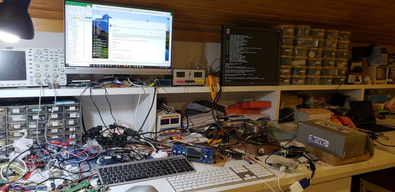
My system here is very basic. I have an old Raspberry Pi, the first ever version, 2011 is printed on the silkscreen. This has never been used, until now. I have an old VGA Monitor that I purchased in the Dayton hamvention 2018 flea market for $5. An old USB keyboard (Apple - actually it is not old, it is never used - but that is another story). And a cheap ($3) HDMI to USB adapter cable. The power supply is a cellphone charger with micro-USB cable that plugs into the Raspberry Pi. I had no problems at all getting this system to work at the first attempt. This is the first time I have ever used a Raspberry Pi.
Steps to flash the firmware
1. Download Garland K6GOG's Raspberry Pi disk image
- For all earlier Raspberry Pi models, download the file named "rasbian-stretch-lite-qrplabs-ttyAMA0.zip" from http://www.youareinvisible.com/qrp-labs/
- If you are using a Raspberry Pi 3, then download the file named "raspbian-stretch-lite-qrplabs.zip" instead. This is because on the RPi3, ttyAMA0 is now the Bluetooth serial port and the UART serial port is now ttyS0.
The file size is 470MBytes so make sure you have a good internet connection etc. This disk image contains Linux for the Raspberry Pi and the proper YIC firmware file, and everything is already set up for you, to be able to re-flash the QLG1 GPS.
2. Install Garland K6GOG's Raspberry Pi disk image on an SD-card
I use a Windows PC with Win10. There is a free application Etcher see https://etcher.io/ which works on Windows. Using it is very simple. Just select the .zip file containing the image (no need to un-zip it), connect the SD-card to your PC using a USB Cardreader and select it, then click "Flash!" and wait for the image to be flashed to the SD card.
If you use a Mac, ApplePi-Baker is a good utility to put the image on an SD card. Further information on installing images for a Raspberry Pi: https://www.raspberrypi.org/documentation/installation/installing-images/
3. Make four connections between the Raspberry Pi and the QLG1.
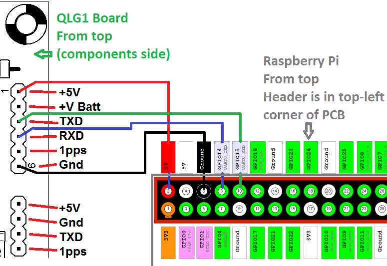
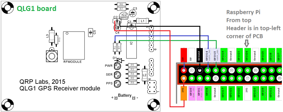
For this step, I am assuming that your QLG1 is already assembled. The connections to the assembled QLG1's 6-pin header are shown below. Do NOT connect the QLG1's 4-pin header to an Ultimate3S kit, QCX kit etc. The Raspberry Pi will supply 5V power to the QLG1.
- Connect QLG1 pin 1 (+5V) to Raspberry Pi pin 2 (+5V) or equivalently, pin 4
- Connect QLG1 pin 6 (Gnd) to Raspberry Pi pin 6 (Gnd)
- Connect QLG1 pin 4 (RXD) to Raspberry Pi pin 8 (UART0_TXD)
- Connect QLG1 pin 3 (TXD) to Raspberry Pi pin 10 (UART0_RXD)
NOTE: it is entirely correct that QLG1 RXD connects to Raspberry Pi TXD, and QLG1 TXD connects to Raspberry Pi RXD. (Transmit talks to Receive, Receive lists to Transmit).
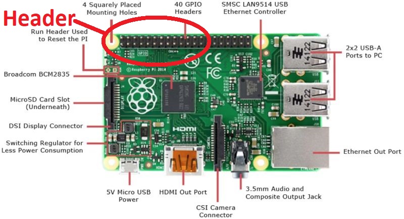
NOTE: older Raspberry Pi models such as mine, have a 26-pin header (2-rows 13-pin); newer Raspberry Pi models have a 40-pin header (2-rows 20-pin). It makes no difference, the pins were are interested in (nearest the top left corner of the Raspberry Pi PCB) are the same.
Here's a photo of a Raspberry Pi model-B+ (for example) showing the location of the header at the top left of the PCB:
4. Power-up the Raspberry Pi, login and Flash
It takes a few minutes for a Raspberry Pi to boot up. Eventually it asks for a login. Use:
Login: pi
Password: raspberry
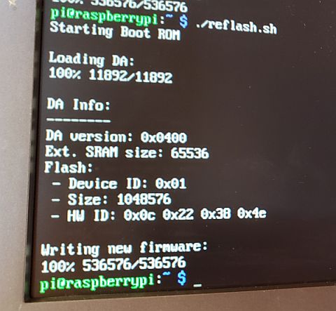
Now it should give you a command prompt: pi@raspberrypi:~ $
Now just type command ./reflash.sh
You should now see some status information as the Raspberry Pi flashes the new firmware to the YIC RF module. This takes about 3.5 minutes on my system. On more modern Raspberry Pi boards it takes about 1 minute. At the end if all is well, you get the lines:
Writing new firmware:
100% 536576/536576
pi@raspberrypi:~ $
I found that sometimes an error is reported. In this case just trying again seems always good enough to resolve the error.
THAT'S ALL! DONE!
In case of wanting to re-flash an un-assembled QLG1 GPS kit
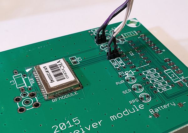
This is also possible, follow all the steps above but now modify step 3 to make connections to the QLG1 PCB (with no components installed), and use the 3.3V pin of the Raspberry Pi. The connections to the QLG1 are made at capacitor C2 (conveniently connects to 3.3V and Gnd) and the top end of R1, R2 which connect to TXD and RXD outputs of the GPS RF module.
- Connect QLG1 left side of C2 to Raspberry Pi pin 1 (+3.3V) - note, we must use the 3.3V pin now, not 5V as above, since we aren't using the voltage regulator that would be installed on the QLG1 board. 5V would be too much for the GPS chip.
- Connect QLG1 right side of C2 to Raspberry Pi pin 6 (Gnd)
- Connect QLG1 top end of R2 (RXD) to Raspberry Pi pin 8 (UART0_TXD)
- Connect QLG1 top end of R1 (TXD) to Raspberry Pi pin 10 (UART0_RXD)
I find that it is sufficient to wire up these connections to two 0.1-inch 2-pin headers, and just loosely insert these into the C2 position and the holes for the top of R1, R2. All the PCB holes are through-plated and the pin headers just inserted into the holes (without soldering) seems to be enough to make a good connection. If there is any intermittent connection during the re-flash process, for example if you wiggle the wires, then the Raspberry Pi console reports an error and the procedure stops.
Everything else is done the same as above (steps 1, 2, 4).
Many thanks again to Garland K6GOG for developing this method, which has been so helpful!