This page will describe the AD9850 DDS module testing and adjustment which is performed deep inside the mysterious QRP Labs factory interior. This testing is carried out on ALL AD9850 modules before inclusion in the Ultimate3 kit, to ensure high quality. The description below may help people who need to adjust an AD9850 module for use in an Ultimate3 kit.
The current U3S kit uses the Si5351A synthesiser module kit, not the AD9850 DDS module, therefore there is no further need for testing/alignment of the AD9850 DDS modules. A great relief, actually...
The AD9850 DDS module supplied with the Ultimate3 kit is similar to modules commonly available on eBay and through other suppliers. However the Ultimate3 AD9850 module is now manufactured to order in a factory. This is more expensive but the modules are evidently of a higher quality. There are two reasons for carrying out the tests and adjustment individually on all AD9850 modules prior to kit shipment:
1) Historically (with the Ultimate2 kits and early runs of the Ultimate3 kit) the modules were purchased in bulk from other suppliers, but it was found that between 15-20% of them failed the below testing. These "fail" modules mostly exhibitted short-term instability of up to several 10's of Hz, that would make them entirely unsuitable for use in a QRSS/WSPR transmitter. Some failed to produce any output at all. This failure rate of 15-20% is unacceptable. The new runs of AD9850 modules manufactured specially for the Ultimate3 kits actually show almost a 100% reliability rate, but the testing is carried out anyway.
2) When supplied from the manufacturer's factory, the blue potentiometer (comparator threshold adjustment) on the AD9850 module board is NOT adjusted. There is therefore no squarewave output from the AD9850 on-chip comparator. Since it may not be easy for many kit constructors to carry out this adjustment, and there are already enough variables, it seems only polite for QRP Labs to supply the module ready-adjusted.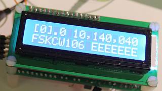
Threshold comparator potentiometer adjustment
To carry out this test, the U3 kit is set up in FSKCW mode at frequency 10,140,040Hz, with a simple "E" message (anything would do), with dit speed set to 106 seconds, and FSK Hz set to 0 Hz. Effectively therefore, the kit is simply transmitting a continuous carrier at 10,140,040. The 106 second dit speed ensures that nothing could possibly change state that could interfere with any measurement.
The kit is powered by a well-regulated, well-smoothed PSU with 5V @ 5A and 12V @ 5A capability, using linear regulation so as to avoid any suspicion of switched mode PSU noise in sensitive receivers etc.
The signal at the DDS squarewave output (pin 7), which is also the same as microprocessor input pin 11, is monitored on a 100MHz oscilloscope via a x10 probe. Note that for these tests, the U3 PA is actually disconnected.
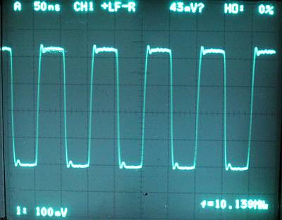
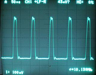
The blue potentiometer is adjusted by eye for the oscilloscope waveform shown below, which is a nice squarewave with 50% duty cycle: the waveform is symmetric, with equal high and low periods. The adjustment is quite sensitive, the tiniest movement of the potentiometer affects the output waveform, and for the majority of the potentiometer's travel, there is no waveform output at all. Note that it is Ok to ignore ringing on the edges, this is not related to the potentiometer setting.
The following examples are NOT correct oscilloscope waveforms:
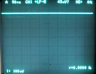 |
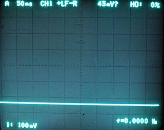
All the way anti-clockwise: This is how the 'scope trace looks when the potentiometer is turned all the way anti-clockwise to its limiting position. Turn the potentiometer clockwise ("right") carefully, until a pulse waveform is seen. |
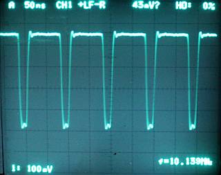 |
Slightly too anti-clockwise: The adjustment is almost correct here, but still slightly too anti-clockwise. There is a pulse output but the duty cycle is not 50%. In this condition the Ultimate3 will produce power output, but much less than it optimally should. Turn the potentiometer clockwise ("right") carefully, just a little at a time! |
 |
Slightly too clockwise: The adjustment is almost correct here, but still slightly too clockwise. There is a pulse output but the duty cycle is not 50%. In this condition the Ultimate3 will produce power output, but much less than it optimally should. Turn the potentiometer anti-clockwise ("left") carefully, just a little at a time! |
 |
All the way clockwise: This is how the 'scope trace looks when the potentiometer is turned all the way clockwise to its limiting position. Turn the potentiometer anti-clockwise ("left") carefully, until a pulse waveform is seen. |
 Frequency stability test
To test the frequency stability, a simple 30m band direct conversion receiver is used, powered from a well-regulated (linear) power supply.
The audio output of the receiver is fed into a laptop PC via a Logitech USB headset whose headset has been cut off and replaced by sockets, so that the USB audio ADC can be used to feed good quality audio into the laptop. This is MUCH better than the mic/line inputs on the laptop.
The free ARGO software is used on the PC in the whole-band, fast vertical scrolling mode. The result should be a sharp, straight line without any instabilities or wiggles. Upon switch on of a new AD9850 module of course, there is some warm-up drift of the 125MHz crystal reference oscillator, which shows as drift of the ARGO line. This is fine, not a problem. What we are looking for is the absence of short-term instabilities that would show up as easily visible wiggles in this line.
The image to the right shows 90 seconds of testing. In practice, 10-20 seconds is sufficient to show any instabilities. You can CLICK HERE to view the full-size ARGO example shown here.
Higher bands, e.g. 10m
Note that the adjustment of the comparator threshold described above is carried out at 10,140,040 in the 30m band. Some kit builders have noted poor output on 10m, which has been resolved by very very slight adjustment of the comparator potentiometer. Apparently the comparator performance is less good as the frequency rises, so the adjustment becomes a lot more critical.