|
|
This GPS receiver module kit includes an extremely sensitive patch antenna, with factory pre-soldered Mediatek chipset RF module. It has three onboard LEDs for visual status indication, 3.3V regulator and power supply filtering, and 5V logic level conversion. It's easy to build and directly compatible with all QRP Labs kits. |
NOTE: The QLG1 GPS module is discontinued as of February 2021. It is replaced by the QLG2 module which has higher performance and more features, at the same price. The above shop link directs to the QLG2 ordering page.
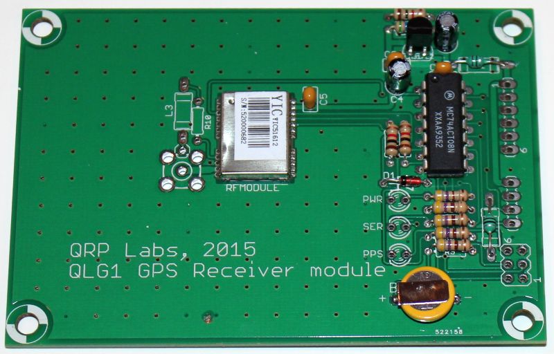
The RF module uses the MediaTek chipset and it is essentially comparable to the QRP Labs supplied SKM61 GPS module. The board size is relatively large (91 x 64mm), this is to provide additional patch antenna gain. Most GPS receiver modules with built-in patch antenna are a compromise between small physical size and sensitivity. If we drop the size constraint, it appears that the antenna sensitivity is optimum with a large patch antenna (25 x 25 x 4mm size is the largest available) and a large 6 x 6 cm PCB ground plane. According to the antenna datasheet the gain is 7.5dBic over that of a 30 x 30mm ground plane. Most small GPS modules are of course smaller than 30 x 30mm.
The board also includes supply filtering, 3.3V voltage regulator, and level converters to provide 5V input/outputs. The connectors are 0.1-inch pitch so they are easy to solder to. The 4-way connector pads section can be connected DIRECTLY to the Ultimate 3/3S QRSS/WSPR TX kit, with no pullups or decoupling capacitors. There are three 3mm LEDs on board, that give a visual indication of what is happening. They are:
Red: Power (always on)
Yellow: Serial data (flashes when the serial data burst is active)
Green: 1pps (flashes on for 0.1s once per second, when the 1pps signal is present)
Advantages of this module, compared to the SKM61 (and other comparable small GPS receiver modules), are:
1) higher sensitivity of built-in patch antenna, due to large ground plane
2) Provices facility for SMA connector and components for external active antenna if you prefer
3) Has onboard power / data / 1pps LEDs for an immediate visual indication of what is going on
4) Proper level conversion for use with 5V systems, not just pull-up resistors like on the SKM61
5) Larger connection pads with 0.1-inch pitch, suitable for easy wire soldering or pin headers
6) Voltage regulation and all components already on-board, no need for anything other than wire, for U3 connection
7) Low cost
8) A kit - fun and educational to build!
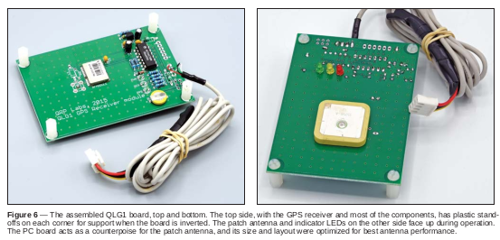
The kit contains the PCB with pre-soldered Mediatek chipset RF module, and all other through-hole leaded components for easy assembly. It also includes four nylon 12mm M3 hex spacers and four M3 screws, for mounting the PCB in an enclosure. The kit is supplied with a 25 x 25 x 4mm custom-manufactured tuned patch antenna. This is installed on the opposite side of the board to the other components. An SMA connector (not supplied) may be fitted if you prefer to use an external active antenna. A 3V rechargeable battery is included, which backs up ephermeris data and can ensure faster satellite lock after short-term loss of power.
Documents
Assembly instructions for the QLG1 GPS Receiver module kit, please click here
RUSSIAN assembly instructions for the QLG1 GPS Receiver module kit, please click here (many thanks Andrey R1CF)
JAPANESE assembly instructions for the QLG1 GPS Receiver module kit, please click here (many thanks Toru-san JG1EIQ!)
FRENCH assembly instructions for the QLG1 GPS Receiver module kit, please click here (many thanks Gilles F1BFU)
Datasheet of the MediaTek chipset RF module
(Thanks to Paul AI4EE for the computer-drawn schematic used in the assembly instructions and the French translation).
Kit photos


ARRL Review of QLG1 in September 2019 QST issue
Paul N1II reviewed the QLG1 GPS Receiver kit in the September 2019 issue of the ARRL monthly publication QST.
CLICK HERE to read the PDF (497K file)
Reproduced with the permission of the ARRL. Copyright ARRL.
Visit the ARRL website here.
Comparison with SKM61
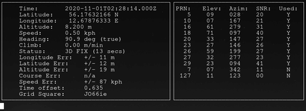
A side-by-side comparison of two U3 kits was made, one connected to the SKM61 and one to the QLG1 GPS receiver (using the U3 GPS Info display feature). On average the QLG1 GPS receiver tracked more satellites than the SKM61 and used more satellites in the fix computation. On average the reported Signal to Noise Ratio (SNR) average was lower, for the QLG1 GPS receiver. This may be because the QLG1 is able to track more satellites, including lower signal strength ones closer to the horizon; this may reduce the average SNR. However I have also read that the "SNR report" numbers are not necessarily directly comparable between different GPS receivers, they are more of a relative measure. More important is that the number of tracked satellites was higher, presumably due to the larger PCB ground plane of the QLG1, as per antenna datasheet.
Connection to Ultimate3S QRSS/WSPR kit, or other QRP Labs kits
Connection to QRP Labs kits is extremely simple due to the onboard 3.3V regulator and onboard 5V logic level converters. All that is required is a 4-way shielded cable between the Ultimate3S kit (or other) and the QLG1. We recommend a few meters of shielded cable, to keep the GPS receiver away from interference. There is no need for regulators, decoupling capacitors or pullup resistors. All of that is already incorporated on the QLG1 board.
QLG1 installed in Ultimate3S kit, by Bri G0MJI
This is the installation of the QLG1 kit with an Ultimate3S QRSS/WSPR kit, with full complement of Low Pass Filters (LPF), and the relay-switched LPF kit, in the official QRP Labs U3 case. Bri is making use of the externally mounted antenna option. He has a short coax with SMA plug on one end and socket on the other, installed from the QLG1 to the back panel. Note that if using the QLG1's onboard patch antenna, you cannot install the QLG1 inside the metal box as this will block signals from reaching the GPS antenna; you should separate the QLG1 from the U3S with a few meters of shielded cable to keep interference away from the sensitive GPS receiver.

Modifications
If the QLG1 is left for a long time unused, the battery might be damaged. It happened in one or two cases I am aware of. The battery retains the downloaded satellite ephemeris data and helps the GPS to achieve a faster lock when powered up (called a "warm" start). The satellite ephemeris data has limited lifetime and in any case in many applications the QLG1 will be used in, such as the U3S kit, and frequency reference projects etc., the unit will be always-on so this feature is not much use anyway. If you get any trouble with the battery, it can be removed. In that case, to get the unit to operate properly, also remove R9 and solder a connection between the + side of C4 and pin 2 of the 6-pin connector (the battery input).
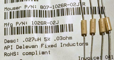
27nH Choke for using external active antenna
Several people have questioned what choke part number to use for the optional inductor L3 that is used when connecting an external antenna. This inductor really isn't very critical, all it has to do is block 1575MHz, so practically any small inductor with approximately that value or greater, should do fine.
But if you want to be precise: Chris K7AZ recommends Mouser Part number 807-1026R-02JTR.
A nice Lego case by Mario IK2CMN
Mario has an interesting solution to the problem of enclosing the Arduino shield kit and QLG1 GPS kit! See photos below!


A note on the external active antenna SMA connector, by Harald DL1HW
Harald notes that the pad (circled in the photo below) has a high risk of short-circuiting to the body of the SMA socket, when the SMA socket is used for connecting an external antenna cable. Harald's solution to this problem is to raise the SMA connector slightly away from the PCB. This is an excellent solution and recommended for anyone who wishes to install an SMA connector for an external antenna. The wire of the inductor should be soldered to the centre conductor of the SMA connector, underneath the board.


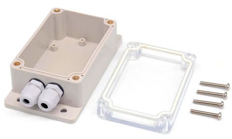 Useful inexpensive plastic case, info from Paul N2EME
Paul N2EME reports that this IP66 waterproof junction box fits very well with the QLG1 GPS kit.
"I just trimmed off 2 of the corner holes as only 2 lined up perfect and there was no need to modify the other two holes."
The box is available from BangGood see https://www.banggood.com/SONOFF-IP66-Waterproof-Junction-Box-Waterproof-Case-Water-resistant-Shell-p-1223669.html?rmmds=myorder&cur_warehouse=CN <
Using QLG1 with a Raspberry Pi (4), comments from Lars-Erik SA7LEJ
1) Connect your Raspberry PI like the "official" guide suggests for flashing (connect 5V/GND/RX/TX.)
2) Enable UART/Disable serial-console in step 3-4.
3) Alter baudrate to 9600 with the command sudo stty -F /dev/ttyS0 speed 9600
4) Follow the guide for setting up gpsd. But replace all occurrences of /dev/ttyAMA0 with /dev/ttyS0
5) Finally i added /dev/ttyS0 to the "DEVICES"-part in /etc/default/gpsd (DEVICES="/dev/ttyS0") to make sure it starts with the correct device at boot.
I can now view gps-data in xgps, cgps, and gpsmon. I have yet to set up time-sync but i will probably go this route. Very happy with my OLG1 - nice and affordable option for bringing GPS to your raspberry :)