Some nice photos and instructions from John VK6JY, who mounted the LCD directly on the PCB but at a 90-degree angle to the PCB, as mentioned briefly in the manual at section 5.3 ("alternative LCD mounting options"). In this case the PCB is "upside-down" in order to view the LCD display the right way up.
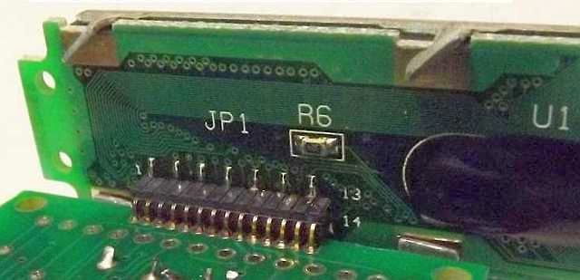
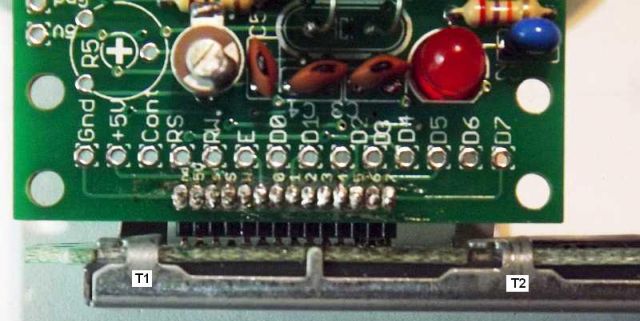
1) Bend tabs T1 and T2 shown in the 2nd photo (see below). Then feed the pins of the LCD into the QRSS kit PCB upside-down, as shown:
2) Tabs that were straightened then gently bent flat to stop fouling the pin bending movement.
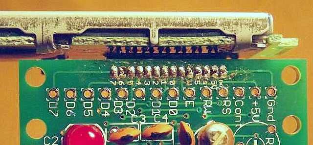
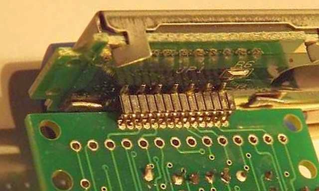
3) Solder side for LCD pins on component side of QRSS board. Also shows folded metal tabs.
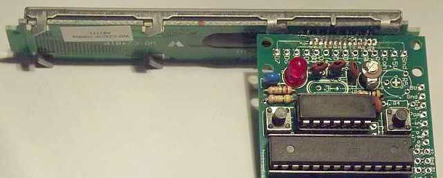
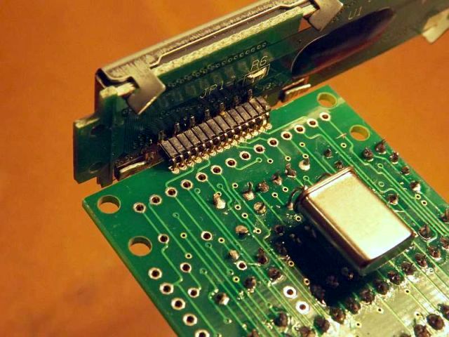
4) General view of completed board. Note the crystal can be soldered to the bottom side, for convenience.
5) Close-up of the under-side of the PCB
6) General view of the underside of the PCB. Note the crystal soldered here to the under-side of the board.
Many thanks to John VK6JY for sending the photos.