 Introduction
Here begins a somewhat questionable quest to amplify the output of a 40m QCX 5W CW transceiver kit to 50W. All components were sourced from the junk box. Therefore this is an interesting story of scrounging as well as simple RF amplifier design. All experiments so far, were limited to 40m. In summary, the results of this effort were:
- A very nice Low Pass Filter made with wooden formers
- A 35W single-ended, single IRF510 amplifier
- A 55W push-pull, dual IRF510 amplifier
As well as the junk box, other equipment used includes a 30V 5W variable lab power supply; 12V homebrew power supply (12V @ 5A, 5V @ 5V all regulated); a big old 50V 20A power supply (ex-BBC); oscilloscope; DVM; and a QRP Labs 20W Dummy Load kit. Yes this is clear abuse of a 20W dummy load but my key-down periods were kept somewhat brief and the dummy load appears to have survived unscathed.
Speaking of which - a significant number of MOSFETs were not so lucky and met untimely and explosive endings. Read on... and remember to CLICK THE PHOTOS for bigger versions.
First: WHY??
Why oh why QRO? Blasphemy!? This is a very good question.
I have always been a QRPer. Until now, I have never had a QSO with more than 5W in my life. I know that I can switch on my 20m or 40m QCX CW radio at any time of day or night (respectively) and within a few moments, I can work someone on CW. Or call a CQ using the programmed message feature of my QCX and someone will answer within a few minutes. I can work stations running 300W, 500W, 600W... and they don't even know my very low power until I tell them, then imagine their surprise. I am sure many of you have experienced this too. I have worked DX, I have broken pileups. All with humble equipment and mediocre (being generous!) operating skills. So why QRO?
Well there have also been occasions when I have wanted to QSO with a particular station, at a particular time, and have been unable to because conditions didn't quite allow it with my QRP power, and I have wished I had a bit more in reserve. Then there are some similar times when the desired specific target station isn't at a favourable angle to my OCFD antenna and so perhaps the signals are some dB attenuated in that direction. Not to mention the 800m high mountain which sits a few hundred meters away to my West, right in line to certain southern European countries, and to date defying all my efforts to move it.
In all these circumstances it might be desirable to have a little bit more power in reserve, for such occasions. And anyway... this project is just unbeatable FUN...
Low Pass Filter
The first job is to construct the Low Pass Filter. The 0.37 inch diameter (T37 size) toroids used in the QRP Labs Low Pass Filter kit probably won't be up to the task of handling 50W. In any case, I may want to experiment with other things too. So let's make a proper QRP LPF that won't burn up under any reasonable circumstances.
The existing QRP Labs LPF kit component values were used, but using bigger components. The capacitors I used are mostly silver mica and have a voltage rating of 250V (much more than necessary for 50W!). For the inductors, I used a piece of strong wooden pole which I think is either intended to be a broomstick or a curtain rail; personally I had intended it as a component of a planned antenna which didn't take place. I sawed off three cylinders from that. The diameter of this wooden pole measured 23mm. I added another 1mm because the wire I used had 1mm diameter, so adding 0.5mm to the diameter on each side for a total of 24mm gives the center point of the wire turns.
I drilled a hole through the diameter of each cylinder about 5mm in from the end; the distance between the holes is 34mm. The holes secure the enameled wire quite tight. They allow me to implement whole or half turns. There are many calculators online for air-core inductors such as: https://www.daycounter.com/Calculators/Air-Core-Inductor-Calculator.phtml and http://m0ukd.com/calculators/air-cored-inductor-calculator/ so I used these to calculate the number of turns required for inductances of 1.38uH and 1.70uH. The result: 10 turns for 1.38uH and 11.5 turns for 1.70uH.
I tend to round DOWN on the number of turns required because there are a lot of assumptions (perfectly tight windings, evenly spaced windings, no coupling between windings, etc etc) and all of these tend to INCREASE the inductance. In the final version I actually removed 1 whole turn from each inductor though there was very little apparent impact from doing this.
Another important point is that air-cored inductors do not have inherent self-shielding properties that toroidal formed inductors have. The magnetic field extends a significant distance from the coil. Therefore coupling can easily occur between nearby coils and this will impact the performance of the filter, allowing RF to jump across (bypass) the filter components. People say air-core inductors should be free of any other coils for 3x the diameter of the coil. Practically that is rather a large distance... and my PCB slab isn't that big. What I did as a mitigation of potential coupling issues was to orientate the 1.70uH middle inductor at right-angles to the two side inductors. The 1.38uH inductors on each side are drilled with two small holes parallel to the axis of the wooden rod, so that I could screw them to the PCB base plate using self-tapping screws.
My copper-clad PCB is bolted to a rather-too-large heatsink from the junkbox. Better too big than too small, at least to start with.
Photos below show the initial placement on the board (left); the assembled LPF, with wires soldered together and added the capacitors, using paralleled capacitors available in the junkbox, to make up the required values (middle); and the spectrum analyzer sweep of the Low Pass Filter characteristic from 0 to 50MHz (right). It looks REALLY good! CLICK for full-size versions.


Bifilar and Trifilar transmission line transformers
A note now about bifilar and trifilar transmission line transformers which were used in these experiments. In QRP applications one would perhaps use some 28awg (0.33mm) wire such as found in the QRP Labs LPF kits (and others), twist some lengths together, and wind some turns on an FT37-43 or FT50-43 toroid. But this isn't a QRP application...
The junkbox yielded some ferrite rods, of the type used for the antenna circuits in old medium/longwave etc broadcast radios. The ones I found first in the junk box, happened to be 8cm long and have a diameter of just under 10mm. It isn't going to be critical - anything will do! I then used some multi-stranded cables, one red and one black, wound neatly in closewound style, around the ferrite rod. I found that about 10 turns fit on the rod. To keep everything in position I used a small piece of 1cm diameter heatshrink tubing at each end to hold the wires, then covered it in a larger piece of heatshrink tuning. The results are visually at least, very pleasing! The black/red wires aren't twisted, and do not NEED to be twisted.
The trifilar coil was made in the same way, this time using a piece of 3A electrical cable, from which the multi-stranded blue, brown and green wires were extracted. Again they were closewound around the ferrite rod and secured at each end with a piece of heatshrink tubing, then a larger outer piece of heatshrink tubing over the whole lot. Although this time there are three wires side-by-side, the wire was also thinner than the bifilar case and so I still got about 10 turns on the length of the ferrite rod.
The photos below should make this clear (CLICK for large size versions). The use of the multi-stranded electrical wiring type cable makes it very easy to wire up, because you don't have any doubts about which winding is which! Nice colour-coding! That is different from the normal QRP case with the identical 0.33mm diameter wire, that you have to check with a DVM to find which wire-ends belong to which windings.


Single-ended, one-IRF510 MOSFET amp produces 35W
 Here's the first attempt at the 50W target.
There's a Pi-network resistive attenuator at the input which attempts to somewhat guarantee an approximate 50-ohm load for the QCX, and keep the amplifier stable. The component values I used (330, 22, 330-ohm) aren't quite right for a 50-ohm 3dB attenuator. The attenuation is a bit more and the impedance isn't right. But don't let's let that bother us. These resistors need to be a bit chunky as they have to handle several watts from the QCX. I don't have a huge stock of power resistors so have to take what I find, that is close enough.
The 7805 voltage regulator provides +5V to the top of the 4.7K bias potentiometer. The wiper is connected directly to the IRF510 gate. The incoming signal is then AC coupled to the gate by the 22nF capacitor shown.
The drain-circuit of the IRF510 contains a bifilar transformer made using a ferrite rod, as described above. This transforms impedance 1:4 i.e. 12.5-ohms to 50-ohms. Then a coupling capacitor to the LPF. The output was connected to a QRP Labs 20W 50-ohm dummy load with an oscilloscope probe across it to observe the peak-peak voltage of the sinewave, and calculate the power.
VERY IMPORANT to note, is that the tab of these cheap IRF type MOSFETs is connected to the drain. It is therefore RF hot. Your heatsink, you do not want to be RF hot... touching it could result in painful RF burns and shocks, and shorting to anything grounded in the shack will also not  end well... all just plain dangerous. So keep the heatsink grounded, then use proper insulating hardware. The best way to do this is with the common blue or grey silicone insulating pads, and a plastic washer insert that fits into the hole in the TO220 insulating the tab from the bolt. The thermal resistance of the silicone pad is about one tenth the thermal resistance between the silicon die of the MOSFET, and the metal tab. Therefore it is not a significant impediment to heat dissipation via the heatsink. Do NOT be tempted to go for an RF-hot heatsink! The diagram (right, CLICK for large image) is from the 10W HF Linear kit manual and explains how to use the insulating washer and insulating silicone pad.
The adjustment of the bias potentiometer is carried out with no input signal. Starting in the fully anti-clockwise position, the wiper voltage will be zero volts. No current flows in the MOSFET drain-source circuit. As the wiper is turned slowly clockwise, you will find that the current SUDDENLY (this is why it should be turned slowly!) increases. This current can be observed on the power supply, if your power supply has current metering, or on a DVM in current measurement mode. The correct operating point for Class-C is when the current just about starts to increase above zero. I aim for this "idle current" to be a few mA if possible, just so that I know that it is very near the ideal point (0 mA) but definitely not too low.
This amplifier was connected to the QCX-40 and keyed briefly., while observing the peak-peak voltage of the nice sinewave on the oscilloscope. The QCX was powered using 12V from my homebrew power supply (do NOT power a QCX with 30V!!) I was pleased that on my 30V 5A lab power supply, I got 35W output from this arrangement. The chart (below left) shows the power output vs supply voltage. Measured efficiency at 30V supply was around 55%.
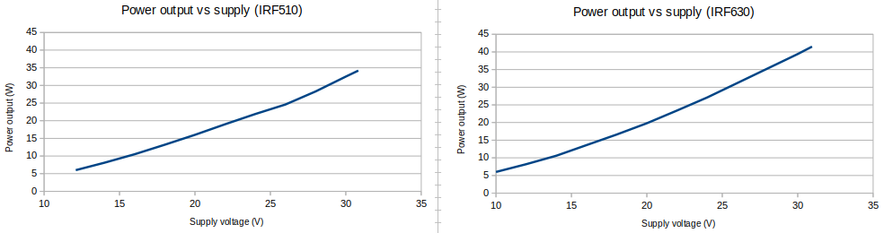
Now, the junkbox also contains a great many different MOSFETs, salvaged from who-knows-what old pieces of dismantled equipment. So I also tried an IRF630 and it yielded higher power output (see above right), up to 41.5W with 30.95V supply which was the maximum my 30V lab PSU would provide. Measured efficiency was 47% at 30.95V supply.
Other MOSFETs from the IRF series, tried in this identical circuit, were IRF634 (produced 35W, very similar to an IRF510) and IRF740 (produced lower power, 25W).
CLICK the photo and diagram below for full-size version.


More POWER...
The difference between 35W obtained (or 41.5W with an IRF630) and the original 50W target is of little consequence in decibel terms. The fun is only in the quest.
Two ideas were tried, to try to increase the power output.
1) Use of a trifilar output transformer, wound on a ferrite rod as described above. This has an impedance transformation of 1:9. The only result of this was that the IRF510 died quite quietly with a hiss.
This was the ONLY time a MOSFET died quietly. All subsequent MOSFET demise was in the form of a loud explosion, accompanied by a flash of light from a spark; the sound is similar to a small gun going off nearby. If you are not ready for it, it will make you jump. If you ARE ready for it, then you will live in fear and trepidation, and it will STILL make you jump. The potent smell of exploded MOSFET lingers in the lab for hours.
2) Use of MORE VOLTS! My variable 30V 5A lab power supply tops out just above 30V. But I do have another, fixed power supply which is an ex-BBC, 50V 20A power supply. A huge thing the size of a large PC desktop or server box, and weighing 35kg. No switched mode here! Just a monster 1kW transformer, a bridge rectifier on large heatsinks, a bank of large electrolytic capacitor cans, another big piece of iron (choke inductor) and more smoothing capacitors. Switching it on results in a Gssssshhhh sound and then a loud hum while it operates.
Unfortunately no MOSFETs survived these experiments. Some exploded immediately. Some exploded on key-down. The ones that exploded immediately, one might speculate, might have gone into some kind of self-oscillation, perhaps a result of the combination of enormous gate capacitance and poor layout, and self-destructed rapidly. Others, perhaps, on key-down just couldn't dissipate the heat fast enough from the TO220 packages to keep cool and thus quickly overheated and met their violent demise that way.
At one point I tried three IRF630s in parallel - similar to the three BS170s in parallel in the 5W PA in the QCX kit! Well.. on switching on the 50V power supply, one IRF630 exploded immediately. Then I pressed the key on the QCX. The remaining two IRF630's briefly produced an enormous 81W RF output as measured on the oscilloscope. BRIEFLY, for less than half a second... then the second IRF630 blew up too. I released the key but a second or so later the third and final IRF630 exploded spontaneously.
I didn't have an infinite supply of these MOSFETs because they were all scavenged from old equipment and found in the boxes of old junk components. So there was no opportunity to further investigate the causes for failure. I was careful not to use MOSFETs with very low drain-source breakdown voltages in the datasheets, so that was not likely to be the issue. Photos below show the aftermath of the destruction (CLICK for larger versions).


After some hours, all my supply of junkbox MOSFETs had either been blown up, or their type number already tested (i.e. blown up), so I retreated to a position of safety: the 30V supply and IRF510, and its 35W output.
I fitted a DPDT toggle switch to allow me to bypass the 35W amplifier during receive; then tuned around the 40m band and found Jay M0UNN calling CQ from Wigan, UK. With 400W and a 2 element Yagi he was booming into KM46 here and actually I could copy him through the amplifier even when the DPDT switch was NOT bypassing it. Anyway I answered his CQ and proceeded to have my first ever QRO QSO, ever... receiving initially a 579 report, later improved to 599. This, at a distance of just over 3,000km. The results of QRO!
Push-Pull, two-IRF510 amplifier produces 50-55W
Not yet ending the unnecessary quest for 50W, I proceeded to try a push-pull configuration. This configuration is based on the QRP Labs 10W HF Linear amplifier kit final stage, which also uses two IRF510 in push-pull configuration. But here I pushed the supply voltage up to 30V, unlike the 10W HF Linear which operates on 12 to 13.8V supply voltage. Another interesting amplifier project does a very similar thing, built by Chris AC2CZ / G0KLA see https://www.g0kla.com/scpa/SimpleCheapPA.php.
This circuit requires THREE transformers:
- Input phase-splitting transformer, a trifilar transformer which can be wound as 11 turns on a FT50-43 toroid since it only has to handle a couple of watts. I used 0.6mm diameter enameled wire twisted together, and 11 turns was what I could fit on the core (not critical).
- Bifilar transformer to supply power to the IRF510s - in the 10W HF LInear kit an FT50-43 toroid is used but I feared that core would not be up to the job in this QRO application, so I re-used the bifilar transformer made from 10 turns on an 8cm long, 10mm diameter ferrite rod (see above section).
- Output impedance transformer with 2:3 ratio
The output transformer with 2:3 turns ratio in the 10W HF Linear amp kit is wound on a type BN43-202 binocular core. I have a lot of these (as I produce the 10W HF Linear PA kit ;-) BUT again, I doubt that they will be man enough to handle 50W. My solution was to use FOUR of these BN43-202 binocular cores. Two end-to-end, then doubled up side-by-side making four in total. These four binocular cores were taped together with electrical tape. Remember that one turn, means the wire passes through BOTH holes of a binocular core. Well, here we have FOUR holes, I know... so to distribute the load on the ferrite I take this to mean, pass the wire through one hole of one pair of toroids, and one hole of the other pair.
The diagram and photo below, should make this clear. CLICK for larger versions!


 Now here's the final circuit of the push-pull amplifier using two IRF510 and a supply voltage of 30V (or just over 30V, as my PSU maxes out at somewhere between 30.5V to 30.95V depending on its mood).
This circuit includes the same attenuator at the input, having about 4dB of attenuation and presenting the QCX with a somewhat stable load somewhere near 50-ohms.
That's followed by T1, which splits the signal into two equal, 180-degrees out of phase halves. T1 is 11 turns wound on a FT50-43.
Now there are two IRF510, each bolted to the heatsink with insulating pads and washers. Each one is driven from T1 via a coupling capacitor, and each one has its own 4.7K bias potentiometer.
The circuit is actually kept as simple as possible because:
- I don't care about linearity. This is not a Linear, for SSB operation. This is just for CW and linearity doesn't matter, I'm following the thing with a 7-element Low Pass Filter after all.
- This is just for a single band, it does not have to be tremendously good at having a flat gain across all HF, I don't care...
- At 7MHz, and with a rough layout not a decent PCB... nothing is going to be optimal anyway
The bifilar transformer T2 is the 10 turns on a ferrite rod, as used in previous sections.
The final output transformer T3 is 2 turns primary, 3 turns secondary; wound on four taped-together BN43-202 binocular cores as described above. That drives the Low Pass Filter used previously and built using QRO components to the QRP Labs Low Pass Filter kit design.
The two trimmer potentiometers to adjust bias, were again set, using the same method described above in the single-ended IRF510 amp, for a few mA of bias current for each IRF510. This is Class-C operation. In the 10W HF Linear kit, they are set up for 125mA each. But here I don't care about linear operation (as I said) and I'm happier for a bit more efficiency and less power dissipation. 250mA at 30V would dissipate another 7.5W of power even on key-up. So biasing them for a few mA, close to zero idle current for Class-C operation, seemed just fine to me.
This time, by the way, I used a different heatsink from previous enormous one, which did not have two convenient holes for the two IRF510s, and because it was always stone cold, seemed too large anyway. So I used what is actually one of the early prototypes for the heatsink used in the 10W HF LInear kit. It has several M3-tapped holes that are in convenient places. The size is 130mm wide by 25mm high and the fin depth is 25mm. It's the same aluminium extrusion as the one in the 10W HF Linear kit but the heatsink in the final production kit is slightly larger at 28mm high and has a couple more holes, as will be required for the QSX kit for which it is designed. There's another identical heatsink prototype under the middle of the board, which has no function other than for the board to stand stably on :-D c
Success! 55W QRO!
SUCCESS! 55W output! Yes... with the PSU set to maximum voltage (a bit over 30V) the output power measures up to 56W. I found that I had not grounded the heatsink, though it was properly insulated from the IRF510 tabs. When I grounded the heatsink, the power dropped a few watts. But still around 52W output. Note that the measured power output of this particular QCX kit at the 12V supply voltage used, into a 50-ohm dummy load kit, was a little under 4 watts. The amplifier gain overall is therefore +11dB; accounting for the -4dB (loss) of the resistive attenuator in the input circuit, this means the IRF510 push-pull final amplifier section is providing a gain of about +15dB.
Measured output efficiency (based on voltage and current indicated on the lab power supply, and 'scope power measurement) is about 45%. Which seems about right for push-pull...
Note that in common with all these amplifier experiments above, if the key is held down for a second or two you can see the power output start to slightly decrease as the MOSFETs rapidly get hot. This is characteristic of MOSFETs which exhibit the opposite effect to thermal runaway on a BJT. In MOSFETs the "ON" resistance increases as junction temperature increases. A useful feature, providing some degree of self-protection.
The final gallery shows some photos and the final circuit diagram. As always, CLICK for larger versions!


This final circuit also contains two SPDT relays used for a simple Transmit/Receive switching application. Even during my QSO with Jay M0UNN I had started to tire of the toggle switch! It's entertaining to recall that I used to use a manual switch for transmit/receive switching for all my operation with my old 1-valve (tube) CW transmitter and solid state receiver. But now I am spoiled by the solid state Tx/Rx switching in the QCX CW transceiver and its beautiful full break-in (QSK) operation.
For the transmit/receive switch in this amplifier I used a very simple configuration consisting of two SPDT relays with 5V coils. I could have used a single DPDT relay but:
- These two relays came into my hands first, as I rummaged through a box of junk scavenged components and:
- It always seems like good practice to keep the input of an amplifier as well separated from the output, as possible. What you really don't want is parasitic capacitance causing leakage between the switch sections of a relay, making positive feedback back to the input if the amplifier and causing perhaps, oscillation, instability and even destruction. Probably less likely here in this lower gain, single-stage application; but still, not a bad idea to adhere to good practice and lessons learnt through hard experience.
Here the two 5V coils were connected in series, with a 560-ohm resistor to make a voltage drop from the 30V supply, accounting (somewhat approximately) for the measured coil resistance. Don't forget the 1N4148 diode to protect the transistor. I used a 2SD882 transistor which was the first seemingly suitable device that fell into my hands during the junkbox rummage. And a 3.9K base resistor.
I connected this to pin 11 of IC3 in the QCX CW transceiver kit circuit board. WHY? Because if you put the QCX transceiver into semi-QSK mode in menu 4.6, then pin 11 provides a good driving signal for the relay switching transistor in the 50W amplifier, which will switch the relays on at the start of keying and then keep them on until a suitable pause (under a second) after keying stops. Connecting to the keying signal (processor output pin 16) or leaving it in Full-QSK mode isn't so wholesome, because there will be a lot of relay-clacking on every key-down, which aside from being distractingly noisy, also feels like it will use up the junkbox relay's remaining lifetime rapidly. Furthermore, by the time the relay has reacted, the QCX output has already started producing power, so the relays will be hot-switching non-negligible RF current and that also feels like it could potentially be not so healthy for the relay. So go for semi-QSK and be kind to the relays.
It would also be possible to do this with an RF-sensing circuit (diode, capacitor) and a delay circuit; to quickly switch on the relay transistor then hang it there in the on state for a delay after the RF stops, long enough to stop it from switching back to receive in between the symbols and characters of the sent Morse code keying. I actually did solder together just such a circuit and it did work. but then I thought: am I making my life harder than necessary? And *IF* I ever do manage to improve my code speed... then the time constant of that resistor-capacitor is going to be all wrong and need changing! OH! I really *AM* making my life harder than necessary, because the magnificent QCX already has exactly the needed signal, AND it is calculated by the microcontroller based on the chosen keying speed in the menu! Sense circuit abandoned.
Next steps
- Well of course this is going to need trying and documenting on other bands too...
- Put this thing in an enclosure because otherwise with this circuit hanging open on the bench, before very long, it is either going to
- a) fall apart or
- b) give me QRO RF burns or electric shocks
CONCLUSION
QRO! What a lot of fun, and education! No components purchased. All junk box sourced. 50+ Watts of no-nonsense CW QRO produced! Some hours of happy experimenting in the lab. I love the beautiful QCX 5W CW transceiver kit more every day (if you don't have one, BUY ONE, at only $49 you can't go wrong!) Amazing FUN, you should try it too.
But please don't excommunicate me from the hallowed QRP ARCI Hall of Fame!
Please don't unilaterally cancel my membership of the beloved G-QRP Club!
Please don't throw me out of Radio Club "72"!