|

|
A useful shack accessory, this is a simple 50-ohm 20W dummy load kit using 20 individual 1K resistors in parallel. Additionally this kit has a diode-capacitor rectifier for detecting the peak voltage of the RF waveform, which may be measured using a DVM. |

The dummy load kit comes with 20 1K 1% 1W resistors, a diode-capacitor rectifier for peak voltage readings using a DVM, and a BNC connector. There are two identical PCBs, and the resistors are sandwiched between them to minimise stray inductance. The PCB size is 1.7 x 1.4 inches (43 x 36mm). The sandwiched-together assembly is about 0.6 inches (15mm) thick. Please note that the BNC connector is threaded but no mounting nut is included.
Assembly instructions
Printed instructions are NOT supplied with the kit. You can download the kit-building instructions for your PCB from the links below.
CLICK HERE to download the kit-building instructions for the dummy load kit.
CLICK HERE to download the FRENCH translation of the assembly instructions (thanks Michel ON4LAU for this!).
CLICK HERE to download the ZCECH language translation of the assembly instructions (thanks Ladislav OK1LO for this!).
CLICK HERE to download the JAPANESE Language translation of the assembly instructions (thanks to Max JK1EDS for this!)
Tips from Volkert DL6BE and German translation
Volkert DL6BE has kindly provided a German translation of the assembly instructions, and a trip (in English) about a different method of assembling the 20 resistors in the PCB sandwich. In Volkert's method the resistors are inserted into one PCB, then the end of the wire bent over to prevent it falling out; the other ends of the resistors can then be calmly inserted into the other PCB, the two PCBs sandwiched together, and finally soldered together. I think it's a neat idea, thanks Volkert! READ ALL ABOUT IT ALL HERE! (23 MByte PDF file)
Kit photographs


ARRL Review of Dummy Load in September 2019 QST issue
Paul N1II reviewed the Dummy Load kit in the September 2019 issue of the ARRL monthly publication QST.
CLICK HERE to read the PDF (497K file)
Reproduced with the permission of the ARRL. Copyright ARRL.
Visit the ARRL website here.
Measured DVM power output indication
This is a simple and inexpensive peak voltage detector and you should not expect amazing accuracy from it. However it can give a useful indication of output power, and even a reasonably accurate one if you calibrate it using a known accurate power meter. The following measurements were made on one kit (as constructed for the assembly manual photography) and power output 0.8mW to 10W. The power measurement was made using the peak-to-peak measurement function of a 100MHz digital oscilloscope. The DVM used was an inexpensive common yellow plastic few-$ type. The two graphs below show the same data, but the second graph (blue line) is zoomed in to show the very low power region 1-400mW.

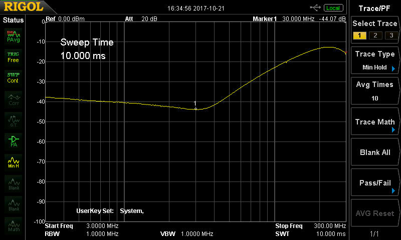
Return loss plot by Jim Kortge K8IQY
This return loss plot by Jim K8IQY shows good performance from 3 to 300MHz. Thanks Jim!
Holding the resistors vertical, by Curt K7ZOO
This is Curt's method for holding the resistors vertical (i.e. perpendicular to the board) during soldering.

